| # |
Description |
Schematic |
Images |
| 001 |
Konami 054986A
Audio module used on several Konami arcade PCBs including Lethal Enforcers, GI Joe, Violent Storm, etc
First
schematic was done in 2017. Second schematic was done in 2022 and has more detail. |


|

|
| 002 |
Konami 005273
Custom resistor array used on almost all 80's and 90's Konami arcade PCBs for the inputs |
 |
 |
| 003 |
Taito 48CR-1
Custom resistor array used on several Taito arcade PCBs for the inputs |
 |
 |
| 004 |
Seibu HB41
Audio hybrid module containing some opamps and caps/resistors used on several Seibu/TAD arcade PCBs including Cabal, Raiden, Toki, Blood Bros and some other non-Seibu
games such as Operation Wolf.
The original reversing was done by AJE_FR
and the schematic is freely available. The usual 'perp' LOSER was (incorrectly) saying the polarised caps are
around the wrong way but the reality is the tantalum caps are AC-coupled so there's no DC voltage going across
them which means they can be any way around as long as they are all the same way. Additionally two of the caps
are back-to-back which forms a bi-polar (i.e. non-polarised) capacitor, so if you don't know what you are
talking about you should probably just keep quiet because I really enjoy exposing losers and making them look
like bigger losers LOL!
Regardless I made some small improvements, optimized component orientation &
location and routed the traces a better way.
The part that usually fails on the original module is the 8
pin chip. This was tested and worked perfect first time. The pic to the right is the first one I built using
parts salvaged from a faulty original module. The part sizes were larger than the proto module design (rev A)
so I had to squeeze them in. The board has since been updated to use parts that are the same size as the
original so parts can be salvaged from a faulty module.
The cost to build this is about $3-$6 depending on where
you get the tantalum caps from. The tantalum caps are the most expensive part and if you salvage them from the old module it will reduce the
cost by 50%.
The module was built and tested on a Blood Bros PCB and works perfect :-D
The schematic (with extra repair info) and board was also updated and posted here (Rev. B, Jan 2024).
Build Level: Intermediate
|
 |


Size: 52mm x 17mm (2 Layer) |
| 005 |
Seibu HB45A
Audio hybrid module used on some Seibu arcade PCBs including Raiden II and *some* versions of Zero Team and Raiden DX. The
actual cost to make this was about $6.00 and most of that cost was the tantalum capacitors.
This was originally reversed by 'Pacman70' (old schematic shown to the right, with corrections by me) and was immediately targeted by the
usual 'perp' as useless and incomplete. You can read it here (mirrored locally). This is quite
funny.
- Firstly the voltage on the module is completely irrelevant. The input power comes from the main board where this module is plugged in. It is of course +12V on pin 9 of the module so any voltage on the schematic doesn't affect it.
- Secondly, the comment says there's no voltage on pin 8 of the NJM4560 op amp (it's just a LM358) and the 2x 2.2uF caps. Erm, they are *clearly* connected to pin 9 of the module so they are automatically connected to the power.
- Thirdly, the comment says the resistors under the NJM2060 op amp (it's just a LM324) are missing. I suggest you get your eyes checked buddy, they are there at R4, R5, R6, R10 & R11 LOL!!!!
So this proves the 'perp' didn't reverse it because if he did he would have known all of that and a lot more. He either paid someone to do it or a
different person did the reversing and he just ripped it off LOL! I suggest next time someone posts a schematic for something you just keep
your big mouth shut LOL!
I reversed a module I have here and checked everything. Once the parts are removed it's actually not that complicated. I scanned the board
and quickly cleaned it up in Photoshop and used that for verification when routing it. I found the only mistake on the other schematic was
C6 value is missing (it's 10nF) and C5 is supposed to be wired to pin 12 of the op amp not to the center of the 2x 33k resistors. All things
considered, the original published reversed schematic was a pretty good effort. Remember anything published is better than hoarding
everything and publishing nothing like the 'perp' does LOL!
Of course I re-reversed everything the 'Guru way' so the schematic is
now perfect and better than everything before it hehe! The footprint of the op amps covers both the 150mil and 200mil versions and the rest
of the design mirrors the original (i.e. no vias). This is effectively a 1:1 identical copy but using modern technology so it is repairable
now. The cost to build this is about $3-$6 depending on where you get the tantalum caps from. The tantalum caps are the most expensive part
and if you salvage them from the old module it will reduce the cost by 50%.
The module was built and tested on a Raiden II PCB and
works perfect :-D
|

New Guru Schematic

old schematic
|


|
| 006 |
Taito TC0070RGB
15-bit RGB DAC used on several Taito arcade PCBs including Chase HQ, SCI: Special Criminal Investigation, Operation Thunderbolt, Cadash, Ninja Warriors, Darius and many others. The legs often break off these or they get snapped in half by careless losers so it's better to just replace it with a proper solid PCB version. The actual cost to make this was about $5. Based on the circuit reversed by JRok. PCB layout by Guru
Build Level: Advanced (150mil IC's, 0805
resistors etc) |

|


 |
| 007 |
G-nano SwinSID
This is based on the SwinSID designed by 'Swinkels' then further reduced by 'x1541' to the nano version and then sold by 'sinchai'. I replaced the silly micro-programming pins with a standard AVR programming header and used all SMD parts, added a LED, optimized the layout and tracks and added a parts listing on the bottom. This has a later bug-fixed firmware. It works fine for most C64 games (including Alien and Lazy Jones) and is definitely better than a dead SID or no SID ;-)
This board replaces a SID 6581/8580 in any C64 model
Reversed by Guru with some small modifications, optimizations, clean-ups etc
Build Level: Intermediate (DIP, QFP32, 0805 resistors etc) |


Size: 17.8mm x 35.6mm (2 Layer) |
|
| 008 |
System 32 Trackball Interface
(replaces 837-8685 and 834-6180)
Reversing and PCB Layout by Guru (more info here)
Build Level: Beginner |

Size: 79.8mm x 99.6mm (2 Layer) |
|
| 009 |
2364 Mask ROM Adapter
This can be plugged into a socket that once required a 24 pin 2364 mask ROM. For example it can replace any of the ROMs on the early C64 motherboards and the ROMs used in the 1541 floppy drive
PCB Design & Layout by Guru
Build Level: Intermediate |

Size: 30.3mm x 17.5mm (2 Layer) |
|
| 010 |
2364 Mask ROM Adapter
Similar to #7, but using a 28C64 EEPROM. This can be plugged into a socket that once required a 24 pin 2364 mask ROM. For example it can replace any of the ROMs on the early C64 motherboards and the ROMs used in the 1541 floppy drive
PCB Design & Layout by Guru
Build Level: Beginner |

Size: 30.5mm x 17.8mm (2 Layer) |
|
| 011 |
1 MEG 28-pin 831000 mask ROM Adapter
Replace your faulty 28 pin 1MB mask ROMs with this adapter which has the same footprint as the original ROM
PCB Design & Layout by Guru
Build Level: Intermediate to Advanced (0.5mm pitch TSOP32) |

Size: 35.6mm x 17.8mm (2 Layer) |
|
| 012 |
C64 & Plus/4 PLA Replacement
Based on the reverse-engineered PLA replacement heavily documented by 'skoe' but modified to use a modern Atmel CPLD (FYI most, if not all the current ~$25 replacements are based on that same one done by 'skoe')
PCB Design & Layout by Guru. Total build price including parts for one complete PCB = $3.50. This is actually the *real* price of any of the PLA replacements you can currently buy.... there's about 2 bucks worth of parts on it regardless.
Build Level: Intermediate |

Size: 35.6mm x 17.8mm (2 Layer) |
|
| 013 |
C64 Joystick Swapper
Now you can have one joystick plugged in and switch between port 1 and port 2 with the press of a button... no more manually unplugging and plugging joysticks and risking blowing up the CIAs in the process. Reversed by Guru from an abandoned protel design which died in ~2015. Re-designed to be much smaller and stand upright
Build Level: Intermediate |


Size: 45.7mm x 27.9mm (2 Layer) |
|
| 014 |
C64 ISEPIC Cartridge
Back in 1984/85/86 this was used to snapshot an entire game running in the memory of the C64 and dump it to a file on the 1541 floppy drive. It's mainly just a novelty now. I reversed this from the original cart I bought back in 1986. I wanted to try to make a full SMD version just for fun..... this is the result.
This is re-designed to be much smaller and use all SMD parts. Note this is not a drop-in replacement for the original PCB. If you want one of those, there is a place selling a drop-in replacement for 10X what this PCB costs. It would be very easy to make the PCB larger to make it a drop-in replacement and the cost would still be less than 1/4 of the one being sold. If enough people contact me and request it, it can be done. But as I said, this is a novelty item now so for the amount of times it will actually be used, this smaller (and thus cheaper!) PCB is just fine.
Build Level: Intermediate |


Size: 57.8mm x 33.0mm (2 Layer) |
|
| 015 |
Amiga A501+ 512k/1MB RAM board
Exact 1:1 clone reverse-engineered by Guru from the original Commodore design. Plugs into the trap door slot and gives the old A500 an extra 512kB of RAM or A500 Plus an extra 1MB RAM. Updated to use a modern non-rechargeable 1/2AA lithium battery or a CR2032 coin battery. Clock parts and battery are optional on A501+ since the A500 Plus already has a clock and battery built in.
Build Level: Intermediate |

Size: xxmm x xxmm (2 Layer) |
|
| 016 |
5101 RAM adapter
This converts a battery-backed 5101 RAM chip to a more modern RAM chip that does not need a battery. This board plugs in where the original chip was. Used mainly in early 80's pinball machines
Build Level: Intermediate |

Size: 28.6mm x 16.2mm (2 Layer) |
|
| 017 |
6116 RAM adapter
This converts a battery-backed 6116 RAM chip to a more modern RAM chip that does not need a battery. This board plugs in where the original chip was. Used mainly in early 80's pinball machines as battery-backed RAM
Build Level: Intermediate |
Size: 28.6mm x 16.2mm (2 Layer) |
|
| 018 |
6264 RAM adapter
This converts a battery-backed 6264 RAM chip to a more modern RAM chip that does not need a battery. This board plugs in where the original chip was. Used mainly in late 80's and early 90's pinball machines as battery-backed RAM
Build Level: Intermediate |

Size: 28.6mm x 16.2mm (2 Layer) |
|
| 019 |
A1091 IDE Controller
This is an 8-bit IDE controller based on the XT-IDE but made into
a Hard Card that holds a common 2.5 inch IDE hard drive, mainly for use in Amigas with PC
Bridgeboards or the A1060 PC-XT Sidecar. This one is designed like the A2091 SCSI controller mainly
for use with Amiga 1000 and A1060 Sidecar, hence the model number given is A1091.
The design is 100% identical to the common XT-IDE open-source design. Basically I just made it into
a hardcard with space for a 2.5" IDE HDD like the A2091 has. This is tested working in A1000+A1060
Sidecar and also with A2088XT Bridgeboard in Amiga 2000 and a 486 PC.
Later I made a version for a regular PC XT as a longer card with support for a 3.5" HDD. This is
basically an equivalent of a PLUS+ Hardcard.... they were all garbage and all dead now lol!
On an Amiga 1000 & A1060, Amiga JANUS is set to E000. Use the BIOS provided here.
I/O address is 300h
BIOS ROM address is C800h
SW1: ON,ON,OFF,OFF,OFF,OFF,OFF,OFF
SW2: OFF,ON,OFF,OFF,ON,ON,ON,OFF
XT-IDE won't autoboot HDD on Amiga Sidecar or Bridgeboard. You must boot XT from floppy disk then in
autoexec.bat transfer control to C: using comspec command....
SET COMSPEC=C:/COMMAND.COM
PROMPT $P $G
C:
Build Level: Intermediate |


Size: 236mm x 94mm (2 Layer) |
A1091 BIOS
A1091 BOM
A1091 Schematic
|
| 020 |
1581 FDD Controller
1:1 exact copy of the Commodore 1581 3 1/2 inch Floppy Drive Controller, including the same footprints,
same silk screening and same weird trace design. Basically this is a reproduction of the original Commodore 1581 PCB but without any signs
of being a reproduction. It essentially looks like the real thing with all the same parts, just made in 2019. Reversed by Guru.
Build Level:
Beginner |


Size: x x x (2 Layer) |
|
| 021 |
Namco NB1 ROM Board
Used to convert any Namco NB1 game to another Namco NB1 game. There aren't that many good games on this system but for example you can convert Super World Stadium 95 to Point Blank or Nebulus Ray using this ROM board.
Build Level: Intermediate |

Size: 96mm x 60mm (2 Layer)
Stock Level: 10 |
|
| 022 |
Fast Load Cart for C64 #1
A reverse of the classic Epyx Fast Load cart. Reversed from the original cart that I bought back in 1984.
Build Level: Intermediate |
Schematic

Schematic (b/w) |

Size: 66 x 60mm (2 Layer) |
| 023 |
Commodore 128 5VDC@4A, 9VAC@1A SMPS
This is the official Commodore 128 switching power supply for the C128 with built-in keyboard (not the C128D).
The weird tracks are exactly like the original 1:1. You can't actually build this because the transformer is not available, although maybe there is an 18V output with center-tapped 9V output transformer out there somewhere? This was just done for fun
and because I needed to see how it works to repair my C128 PSU. Note this also works with the C64 ^_^
Total cost wouldn't be much but good luck getting the transformer ;-)
Build Level: Beginner |
Schematic

|


Size: 92mm x 38mm (2 Layer) |
| 024 |
Commodore 64/128 Quick Cart
This is a simple C64/C128 cart with a rotary selector that will allow you to select up to 64 8k
images or a combination of 8k and 16k images in any order. It supports 8k, 16k and Ultimax C64 images, and 16k C128 images. No need to build
the overly-complicated Versa cart, this does everything you need and more using a simple design with simple parts. It takes less than 10
minutes to assemble and is extremely simple to use. I made this for a fellow Aussie who runs a youtube channel called "The Retro Channel" so if you
check some of the vids there you can see this thing in action :-)
Total cost is about $5
Build Level: Intermediate (back side has a few simple SMD parts but these are *VERY* easy to solder by hand) |


Size: 58mm x 49mm (2 Layer) |
|
| 025 |
Galaxian Multi-Game
This was designed by ex-MAMEDEV Mike Coates and is a project from a few years ago which is
still available on his website. It was 3 separate PCBs that allow a stock Galaxian board to run many different games. Back in the day the
boards were hacked to run the games. With this new board, instead of having to hack the board, all the game ROMs have been fixed to run on a
stock board. This covers all Galaxian boards including the original Namco and Midway boards and bootlegs, including short bootlegs with 2
stacked boards. So you just plug this in and you get ~20 games for free.
I contacted Mike and he was ok with doing some extra software work to support my changes so I made the following improvements:
1. Made a proper schematic because the original was just the PCB routed directly in a PCB layout program. This allow the ERC/DRC to be used.
2. Fixed a few not-optimal connector positions so the joining cables route across the board cleaner.
3. Made one single PCB with separate boards. Use a hacksaw blade to separate them.
4. Re-routed the entire 3 boards to make them more professional instead of like spaghetti auto-routing ;-)
5. Changed the main battery to be a 1/2AA lithium for longer life and added holes to fit a 1/2AA battery holder.
6. Added a 2nd back-up battery for the battery-backed RAM. Removed to reduce complexity as a 1/2AA lithium battery can last 6 years in standby mode.
7. Replaced some DIP parts with SMD parts to make room, to improve the trace layout and make the board smaller. SMD parts are also cheaper ;-)
8. Increased RAM size using an 8kB SRAM or 32kB SRAM (jumper selectable). Functionality does not change, this is more to cover parts you may have in stock.
9. Added the functionality to use a non-volatile FRAM chip so the battery and DS1210 chip are not required.
10. Added a cool logo :-)
With the RAM updated to 8kB or 32kB more high scores can be saved, although currently none of the games support more RAM but this might
change in the future when the supported games are updated. The existing games will not save more high scores unless they are updated. It
just means that the capability is there if someone wants to add more high scores to the supported games, or add support for more games. The
GAL will need to be changed to a GAL20V8 because at least one more pin is needed and of course then re-routed. This is still a
work-in-progress because I'm waiting for Mike to update the GAL to support the FRAM and larger SRAM.
Update: The new GAL has been done and is a GAL22V10. Everything is routed and as an added bonus, in the empty space I made a Dallas
DS1225 Battery-Backed SRAM Module. It isn't used for Galaxian it's just a bonus. This can be used (for example) in a pinball machine that
uses a battery-backed 6264 SRAM... just remove the battery and plug this thing into the socket. Now I just need to get some PCBs made and
test it.
Total cost is not known yet but likely about $20-$30
Build Level: Advanced |


Size: 121mm x 87mm (2 Layer) |
|
| 026 |
Sega SC-3000 Multi-Game Cart
Full schematic for a Sega SC3000 multi-cart with 4MB capacity. This holds basically every SG1000 and SC3000 game ever made.
This was produced by some guy in New Zealand. A local friend has been wanting one for several years but the
NZ guy seems flakey and never got back to him. So when I got hold of one I reversed it and 'problem solved'. I re-routed it properly, fixed
a few mistakes and added a cool logo. This one is done properly, from the fingers to the silkscreen to the routing (which was previously a
big spaghetti mess), now all done the right way. I also changed the jumpers to pre-connected solder blobs and put them on the back side. If
the jumpers need to be changed the center track can be cut, but as they are supposed to be all shorted by default you shouldn't have to
touch them under normal conditions. This has been built and tested and worked perfect on the first try ;-)
Total cost is probably about $10-$20 depending on what parts you have laying around. The BOM (Bill of Materials) is listed in the provided
schematic and takes about 30 minutes to assemble :-)
If you want to print your own case there's a 3D print SG-1000 case on thingyverse
here or use an old SG-1000 case.
Build Level: Beginner |
Schematic


Size: 93mm x 72mm (2 Layer) |
|
| 027 |
MOS 8701 Reproduction
A very tiny PCB that can be used to replace the custom MOS8701 used in the Commodore 64. It is built
with off-the-shelf common and cheap parts.
Total cost is probably about $3.
Build Level: Intermediate to Advanced (small SMD parts) |

Size: 19mm x 11mm (2 Layer) |
|
| 028 |
Sega Model 3 Drive Feedback Board
This board controls the feedback on Sega Model 3 games and a few other Sega games that use
this same board. |


|
|
| 029 |
IGS PGM Cave bootleg
This is a simple IGS PGM board-set you can make that plays 3 Cave bullet-hell shoot'em-ups....
Espgaluda, Ketsui and Do Donpachi Dai-Ou-Jou.
This is an improved version of the IGS PGM board-set hack that runs decrypted bootleg Cave ROMs for
Espgaluda or Ketsui or DoDonPachi DaiOuJou. A full surface-mounted version will follow soon at #36 below. These are all 2-layer boards
because 4-layer boards are not required if you know how to route traces properly. Plus 2-layer boards are much cheaper. The track spacing is
increased to a minimum of 0.25mm. A lot of noobs use the minimum 0.13mm spacing and 0.2mm vias just because the PCB manufacturer says they
can do it but that doesn't mean you should do it. They don't realise how this affects reliablility and repairability... especially 0.2mm
vias.... the reason most mid-late 90s and newer arcade PCBs are dead now. Don't use minimum track spacing unless you have to. These boards
are not that complicated so there's no need for such tight spacing.
I have also provided the full schematic.
This has been tested with all three games and works perfect :-D
Build Level: Intermediate (basic soldering skills but requires EPROM programmer) |
Schematic


Size: 182mm x 121mm (2 Layer) |
|
| 030 |
IGS PGM Cave bootleg - SMD version
Same as above but using SMD parts. The main program ROM, GALs and resistor arrays have been
left as through-hole parts for convenience. The smaller SMD non-polarized caps are on the back side of the board. The SMD parts have been
re-routed properly. I haven't bothered to re-route the entire thing because I'm busy with the next job and I don't think it's that important
but I might go back and do it later. |

|
|
| 031 |
DIP42 32Mbit byte-mode EPROM adapter
This adapter is used to replace a DIP42 mask ROM that has been programmed in byte mode
with TSOP48 flash ROMs. There are a lot of mask ROMs on Namco and Konami PCBs that use byte-mode programming. Anyone repairing arcade PCBs
will know mask ROMs are beginning to fail now quite often and there's no off-the-shelf DIP42 replacement available for those specific parts.
This adapter solves that problem.
This is actually pretty complicated and has a lot of internal traces too... this can only be done with 4
layers if you want to maintain the same DIP42 footprint as the original chip.... which this does ^_^
Build Level: Intermediate to Advanced (SMD parts) |


Size: 53mm x 17.7mm (4 Layer) |
|
| 032 |
DIP42 32Mbit byte-mode EPROM adapter
Same as #31 but using a DIP42 EPROM. Tested working on Tekken 2, Soul Edge and Point Blank 2.
Build Level: Beginner |


Size: 58.4mm x 38.1mm (2 Layer) |
|
| 033 |
TAITO GXC-01 / GXC-02 / GXC-03 / GXC-04 Protection Device
This is a 1:1 reversed schematic of the TMS320C10 protection circuit from a bootleg Sky Shark PCB. This same board was plugged into an
original Taito Sky Shark PCB and worked fine. The board is actually two separate circuits. The bottom section with logic is simulating a
GXL-02 custom chip and the top section with MCU and ROMs is the GXC. The bootleg board uses a stock (not-programmed) TMS320C10
microcontroller wired up to 2 EPROMs and set to use external ROM. The schematic also shows a way to use it with a single 16-bit flash ROM.
Given this info it would not be difficult to make your own reproduction Taito GXC-0x board to replace any of the TAITO GXC chips.
Hishou Zame    - D70011U GXC-01
Flying Shark   - D70012U GXC-02 \
Sky Shark      - D70012U GXC-02 | Same
Wardner        - D70012U GXC-02 |
Pyros          - D70012U GXC-02 /
Kyukyoku Tiger - D70015U GXC-03
Twin Cobra     - D70016U GXC-04 \
Demon's World  - D70016U GXC-04 / Same
The ROMs are available in MAME because years ago I sacrificed some original chips to get them decapped and the ROM was successfully
extracted. Now it's time to re-create the protection using this board and get my games working again.
There will be two versions available. One for beginners using all DIP parts and one for more advanced people using surface mounted parts.
The PCB and gerbers will follow later.
Build Level: Beginner
Cost: Probably $15 or less |

Schematic

|
|
| 034 |
DECO CPU-7
Custom potted CPU module used on a few Data East games such as Burger Time and Zoar.
First version was done back in February, 2009.
2nd version was done in September 2025 using Eagle and has more detail including the pull-up resistors and parts list. I
wanted to get my Zoar PCB working again as the original module was reversed but I lost the module PCB somewhere over
15 years ago so I made a new PCB using my schematic. It works and my Zoar is working again :-) |


|


PCB Gerbers
|
| 035 |
DD1718PA Boost Module
Small module used to get higher voltages from a lower input voltage. This will output positive AND negative voltage. Simply change R1 to get a different output voltage. |

|


|
| 036 |
Schematic: Namco System 23 main board
This is an 8-layer board. This took around 12 hours per day full time for 8 weeks to
reverse. As well as showing all the connections, all clock signals on all chips across the entire board have been measured and noted on the
schematic and brief descriptions of what all the custom chips are doing, as well as some chip-related repair infos. The schematic is a
single sheet approximately 2 meters square. To give you an idea how big this is, the NAMCO SYSTEM 23 text at the top is 100mm high. Yes,
really. This is a preview. The actual pdf schematic is not publicly available to avoid complaints from people peeing their pants when they
see it ;-) |

|

|
| 037 |
Taito Cadash RS-422/RS-485 Communication Schematic
Cadash is one of the few 80's games that has basic networking built in. It can be hooked up to another Cadash board for
2 player gaming. This schematic shows how the MCU is hooked up and the wiring of the inter-connect cable. |

|
|
| 038 |
COSMO by TDS & Mints FULL Schematic
This game runs on Taito 3-board color Space Invaders hardware with a custom top board added. I don't recall how long this took to reverse
and draw but it was at least a few weeks. This includes the special top board schematic including documenting the 8 connectors and where the
50+ wires are joined to on the main boards, as well as full schematics of all the specific Taito PCBs used on this game.
This is a
preview jpg. The actual 'readable' pdf will be released later after the game is fully working in MAME. I suggest one of the known developers
with many years of experience with TTL logic figures out the emulation, fixes it and more of these special schematics may be done for other
games to improve the emulation.
A video of me playing the game can be seen on my youtube channel here. |

|
|
| 039 |
Atari 2600+ cart #1
Full schematic for a simple Atari 2600 cart that can select up to 16x 4kB (FIXED SIZE 4kB
ONLY) ROMs using a (ghetto) 4-position DIP switch. This is a reverse of the 10-in-1 pack-in cart that comes with
the A2600+. It uses a single SST39VF512 (64kB x 8-bit) TSOP32 flash ROM with only 40kB used and the remaining 24k
blank (00-filled). This isn't particularly exciting and obviously we can do MUCH better with almost no effort! See
the next item for something very similar but far more useful ;-) |

|


|
| 040 |
Atari 2600+ cart #2
Full schematic for a simple yet much more useful Atari 2600 cart that can select up to 256x 4kB ROMs using 2x
16-position hexadecimal rotary switches. This rotary switch is what should have been shipped with the A2600+. It uses a single 16M-bit (2MB)
TSOP48 flash ROM. 256 x 4kB = 1MB but I have plenty of 29F016 flash ROMs in stock so that's what I'm using. Since the ROM is pre-selected
this cart will work with the A2600+ unlike most other multi-carts that don't work because the 2600+ is a ROM dumper and tries to dump the
ROM then run it from local RAM. |

|


actual PCB produced |
| 041 |
Atari 2600+ cart #3
A nice Atari 2600+ multi-cart that uses a RPi pico to defeat Atari's non-support of multi-carts lol. The pico
emulates a 4k, 8k, 16k or 32k ROM and the switches allow hard selection of a bank that the A2600+ can't detect so it just loads the ROM
thinking it's a standard cart with the pico seamlessly taking care of bankswitching. This is a work-in-progress with my usual hex rotary
switches added and also using proper level shifter chips. Additionally a 74HC165 is hooked up to read the switches using only 4 GPIO pins.
Previously 4 GPIO pins were being used to read a 4-position DIP switch resulting in a maximum of 16 games selectable. Now with 2 rotary
switches the maximum selection is 256. If more GPIO can be found (only 1 exposed GPIO is free, but 4 more are available at the test points
when some parts are removed) support for 7800 ROMs may be possible.
This will need code changes to make it work with the 165 but it
seems the guy who was doing the original project coding has dropped off the side of the planet like a lot of random people do :-/
If I
ever get this working I'll post full schematic and gerbers but at this stage it's a non-working prototype preview. |
|

|
| 042 |
The Simpsons Video Schematic (THE MISSING PAGES)
These are the missing video section schematic pages (2) for Konami's The
Simpsons arcade PCB. It is drawn using the same Konami style from 1991 so that it blends seamlessly with the existing partial schematic to
make it complete. It also includes the same logo/title block, sheet border, signal names and across-sheet signal references. Additionally,
Konami schematics show the custom chips as very long rectangles but in order for it to be more useful as a repair aid I drew the custom
chips as they are in real life, as squares and with in-order pin numbers. Print onto a single sheet of A3 paper (use both sides) and insert
into your original Simpsons manual for completeness. The schematic is large so zoom in to at least 300% to read it.
As for repairs, aside
from all the nasty Fujitsu logic chips used on these boards that fail, note the most common custom chips failures are a bad 053247 (sprites)
or a bad 051962 (backgrounds). These customs contain internal RAM and if you know anything about PCB repairs you will know RAM failure is
the most common fault on any PCB. If you have major sprite or background faults use the schematic to check the address and data pins and
most likely you will find some dead pins. Of course do that AFTER you have checked/replaced the ROMs/RAMs and connected logic.
There are
no plans to update this but if any errors or omissions are found/fixed there will be a note about it and the new version will be posted
here.
Initial Release: April 9, 2024.
Update (1) May 20, 2024 - Increased text sizes to match the original when printed at the
intended A3 size. |

|
|
| 043 |
Konami 056820
RGB video signal drive module used on several Konami arcade PCBs including all
Konami GX games, all DJ MAIN games (beatmania etc) and others.
The common fault is a failed tantalum capacitor or failed 78M05 5V regulator which are easily uncovered and
replaced using hot air. In most cases unless the module is broken in half (which is a high possibility given
it's made of thin ceramic) you can just fix the original module :-)
If you want to make your own the cost is less than $2 complete including the PCB and all parts. If you do, I
suggest pay the extra fee to have the silly batch number removed as there is no place for it on the board due
to the small size and it will spoil the look of it.
|

|


PCB Gerbers
|
| 044 |
Pi JAMMA
This is an interface board allowing a RPi 3B or 3B+ to connect to any standard JAMMA arcade cabinet. The software shows some
games which can be selected with the joystick and played. The software is a bit janky and needs work but it is usable. The trace routing was
also the usual amateur mess. I took the existing janky board and made it better, using more common parts and removing some parts that do
nothing. Additionally, the original was using a silly AN7511 mono amp chip that costs $15 LOL! I removed it and used a cheap stereo amp
module. For any game that outputs stereo I now get sound out of both left/right cabinet speakers if it is wired for stereo. If there is only
1 speaker it outputs dual mono. Either way, now there's a choice. It also uses a cheap chinese HDMI to VGA converter box to convert the Pi's
HDMI video output to RGB so it works with any 15kHz arcade monitor with settings to output standard 31.5kHz VGA to an LCD monitor. There was
also many routing changes/clean-ups, removing holes for a bunch of parts that are not populated, fixing the Pi mounting holes to be the
*actual* standard and documented spacing 58mm x 49mm and removing a lazy jumper wire (LOL!) and re-routing that trace on the PCB. The
updated schematic, BOM and gerbers will be published later after my new version is built and tested.
|

|
Schematic/BOM (coming soon)
PCB Gerbers (coming soon)
|
| 045 |
Midway Space Invaders
1:1 *exact* reproduction of the Midway Space Invaders L-board. This is an officially released version that
Midway called the cocktail version. It uses an L-board that has all TTL logic and doesn't use the uncommon shifter chips so it can be
repaired no matter what the fault is. I suspect Midway were having trouble sourcing those shifter chips and redesigned it to use common
logic instead. Lucky for us since that makes it 100% reproducable. Primarily this was made to convert a bunch of junk Midway 8080 games to Space Invaders. But the official
schematic has some errors so this schematic fixes them and is 100% accurate to the real PCB. Maybe someone will look at it and fix the bad
fire sound in MAME ;-)
|

|


PCB Gerbers (coming soon)
|
| 046 |
MB834100 mask ROM to AM27C400 EPROM Adapter
This adapter can be used to replace any MB834100 mask ROM on any PCB. They were common on
Taito boards but it will work for any game that requires a mask ROM with the same pinout. You might see scumbags selling these for $$ but if
you're smart you'll just make your own adapter for $2.
|

|


PCB Gerbers
|
| 047 |
Sound Blaster MCA reproduction
This is a modern reproduction of the Sound Blaster card for IBM Microchannel PCs. I didn't reverse
this, I only modified it slightly to make it look more authentic:
- Tidied up the IC location texts
- Removed all the silly b.s. texts and silly logo
- Added a proper Sound Blaster logo
- Added proper board numbers / copyright texts
- Added chip part#'s to all ICs for easier building
This was done for Epictronics and you can watch a Youtube video about it here.
The original project is here (SB1.0 repro) and here (SB MCA repro). These have of course been backed up locally in case they are taken
offline ;-)
|
|

PCB Gerbers
FIRMWARE (8751 MCU & CPLD)
|
| 048 |
Sega Model 1 Sound Board Schematic
|

|

Work-In-Progress
|
| 049 |
Commodore C128D Internal 1571 Disk Controller "C128D DISK"
This is a 100% perfect 1:1 reproduction of the 1571 disk controller inside the plastic C128D.
Reversed by Guru in June/July 2024. Time taken was approximately 1 week from start to finish.... yes I'm very good at doing this ;-D
While this was an interesting reversing project for me (to help a local guy with a C128D and a weathered controller board), this will
probably only appeal to maybe 2 or 3 people who have a plastic case C128D with a broken and unrepairable internal C128D disk drive
controller board. By unrepairable I mean corroded beyond repair.... if you just have a non-working floppy drive the boards are pretty easy
to fix so just fix your board, no need to replace it with another one. It's basically all off-the-shelf parts except the read/write hybrid
and the 42 pin gate array. Neither of those parts are known to go bad (yet) so just replace all the other stuff on your board (or find the
actual fault and fix that) and your floppy drive will be working again. Note the 1571 double-sided drives are known to develop open
read/write heads so if your drive has no resistance on the read/write connector wires (consult the 1571 service manual for info) your drive
is toasted and there's nothing you can do about it... replacing the controller board won't fix your machine ;-)
|
Schematic
Schem is same as Commodore
'C128 INTEGRAL DISK' schematic just newly drawn
so it is clean, readable and has some small corrections. |


5 PCBs (just arrived)


Update 3rd November 2024 - Tested and worked perfect 1st time :-D
PCB Gerbers (coming soon)
|
| 050 |
Commodore FDD hybrids H36A2U57, 251853-01 and 251853-02
As part of the previous C128D DISK project I also decapped and reversed all the floppy drive read/write hybrid modules that are used in
Commodore floppy drives such as the 1541B/C, 1551, 1571 and C128D DISK Controller.
These are all 1:1 reproductions of the original modules. After building and testing these they will be available. Note however, these are
not a commonly failed part so making and building these is not really necessary. They are also using a lot of tiny SMD parts so they are not
that easy to build and because the parts are very dense the footprints are reflow types so they require hot air for soldering and
can't be hand soldered.
- The original H36A2U57 is used in 1541B/C, 1570, 1571 and C128D DISK. It uses a phenolic resin PCB with parts on both sides of the board and no
vias. There are wires at the top to jump traces over to the other side of the board. The repro uses vias at the top so the loop-over wires are not required.
- 251853-01 is used in 1541B/C, 1551, 1570, 1571 and C128D DISK. It uses a 'modern' fiberglass PCB and vias with parts on one side of the
board. This is the easiest version to build and actually the only version worth building.
- 251853-02 seems to be a heavily cost-reduced version only used in 1541B/C and requires some parts changed on the main FDD controller PCB.
The part swap info is documented in one of Commodore's TechTopics documents, Issue 11, 1985. It uses a ceramic PCB, has parts only on one
side and has vias. The actual part count is much lower as most of the resistors are printed onto the ceramic substrate. My guess is this was
not used much and later abandoned since later drives like the C128D DISK board use the H36A2U57 or -01 module.
H36A2U57 and 251853-01 are functionally and electrically equivalent and can be used in any drive. For the 1541B/C drive simply change out
the required parts as per the Commodore TechTopics document and use a -01 module.
For repairs you only need to build the -01 module. The -02 module should be avoided and any 1541B/C should be converted to use the -01
module. All other drives can use the -01 module as-is without modifications. Do not use the -02 module in any other drive unless the
original drive is using it. In this case please contact me and provide photos of the PCB so the component changes can be documented. The
component changes for the 1541B/C drive using PCB 251854 (ASSEMBLY #250448) are documented in Commodore Techtopics Issue 11, 1985.
NOTE! Due to the difficulty of decapping these hybrids and some parts not being 100% identified because the SMD code was not visible, this
project is stalled. To continue this work more hybrids must be decapped and compared to verify the parts. The hybrid connects to the floppy
drive heads so potential head damage can occur if there is a mistake so great care must be taken to double verify everything. If you can
help provide hybrids for decapping please contact me.
Update: 3 more hybrids have been obtained... the RE work continues....
|
Schematics
(coming soon)
H36A2U57 Schematic
251853-01 Schematic
251853-02 Schematic
|
H36A2U57

251853-01

251853-02

PCB Gerbers (coming soon)
|
| 051 |
Police Trainer Full Schematic
Reversed by Guru in July 2023. |

|
|
| 052 |
Truxton / Tatsujin Schematic (sprite section)
This was done to help fix a Truxton PCB with a sprite fault around October 2023. I fixed it so I have no desire to finish this but maybe it is useful for someone. Reversed by Guru in October 2023. |
_thm.jpg "Click to view")
|
|
| 053 |
Namco NB-1 and Gun Board Schematic
Full NB-1 main board schematic, gun board
schematic and gun wiring diagram for Namco NB-1 hardware. This board runs games like Point
Blank, Nebulus Ray, Great Sluggers 93/94, Super World Stadium 95/96/97 and J-League V-Shoot.
The main board schematic is a single 4A0 sheet (2.37M x 1.68M). Reversed by Guru in March/April/May 2026. |

|
|
| 054 |
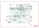
Atten 850D Hot Air Station Controller Board
This is a reverse of my Atten 850D
Hot Air Station control board that failed near the end of June 2026 after roughly 25 years of
use.... not too bad ;-)
It was repaired with the help of the schematic I made to aid in understanding how it works. Unlike all
the new modern stuff, this uses all common off-the-shelf parts so it can be easily repaired.
The fault was a shorted BT136 triac and a melted 24V transformer with center-tap (12V 0V 12V).
The triac was replaced with a more-beefy BT139 and a replacement transformer was acquired and
fitted and the unit works fine now. The PCB didn't need to be reproduced but in order to get
the schematic 100% accurate I had to scan the board, use that overlaid on top as reference and
route all the traces exactly like the original and that found a few mistakes that were
corrected on the schematic so that the traces then routed the same as the original board. The
PCB repro was simply part of the reversing process and I am not going to make this repro PCB.
This has obviously not been assembled or tested but I see no reason why this would not work
given the schematic is verified 100% correct.
|

|


PCB Gerbers
BOM
|
| |
More coming soon..... |
|
|