
1st December 2017
Some more of my To-Be-Decapped chips have been decapped by CAPS0ff.
This time we have all of the Sega Model 2 chips (#211-#218)
While you may think that this will help MAME's emulation the answer is "probably not". While true emulation is now possible, emulating an
additional 4 or 5 DSP's in MAME's Model 2 driver will kill the speed to nearly zero and a snail will travel faster. It would be nice if
ElSemi re-surfaces and updates his great Model 2 Emulator to support the DSPs with true fast emulation, although that's probably unlikely to
happen.
Anyway, those chips have also been marked green on my Decapping Status Page
There's more news and pics of the decapped chips on the CAPS0ff blog.
Please support CAPS0ff with funds if you can so more chips can be decapped.
17th November 2017
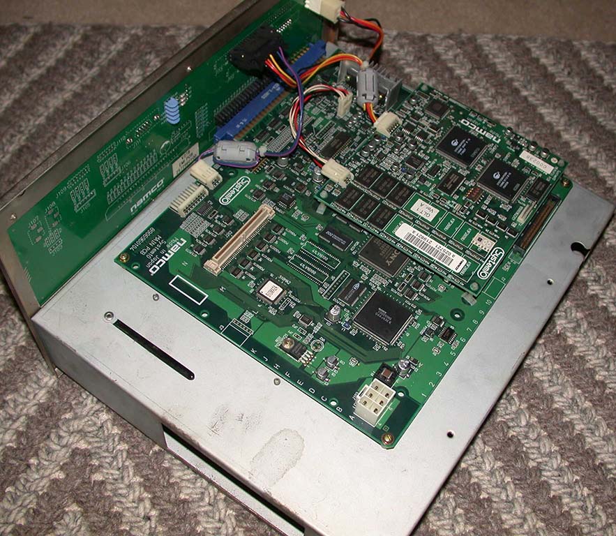
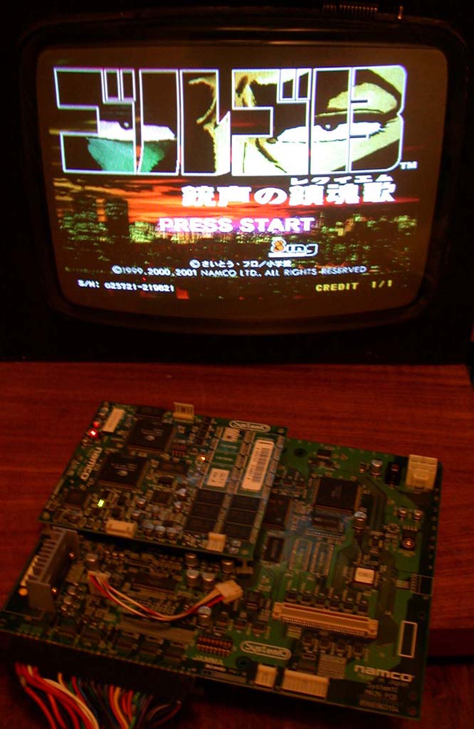
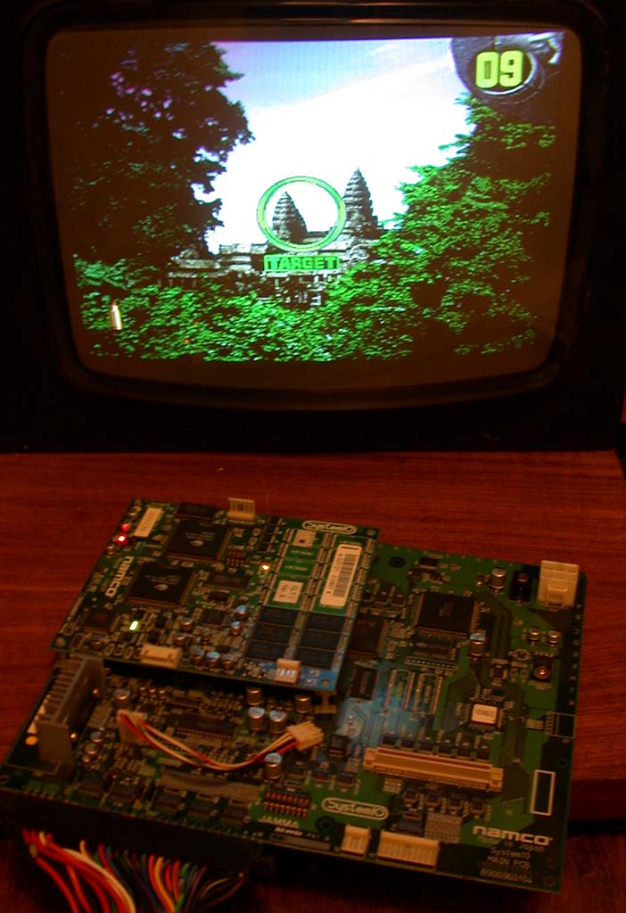
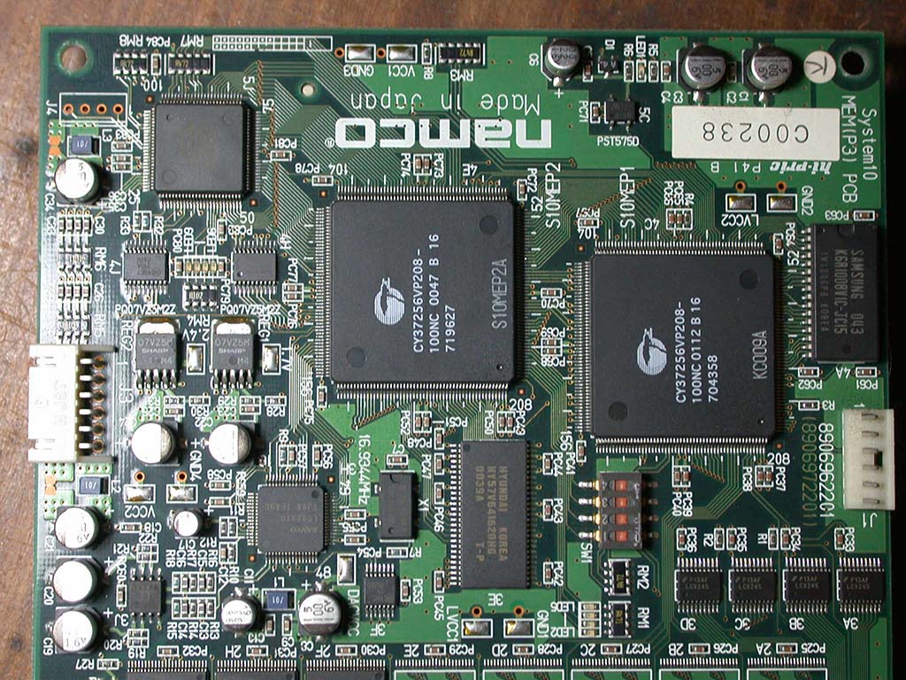
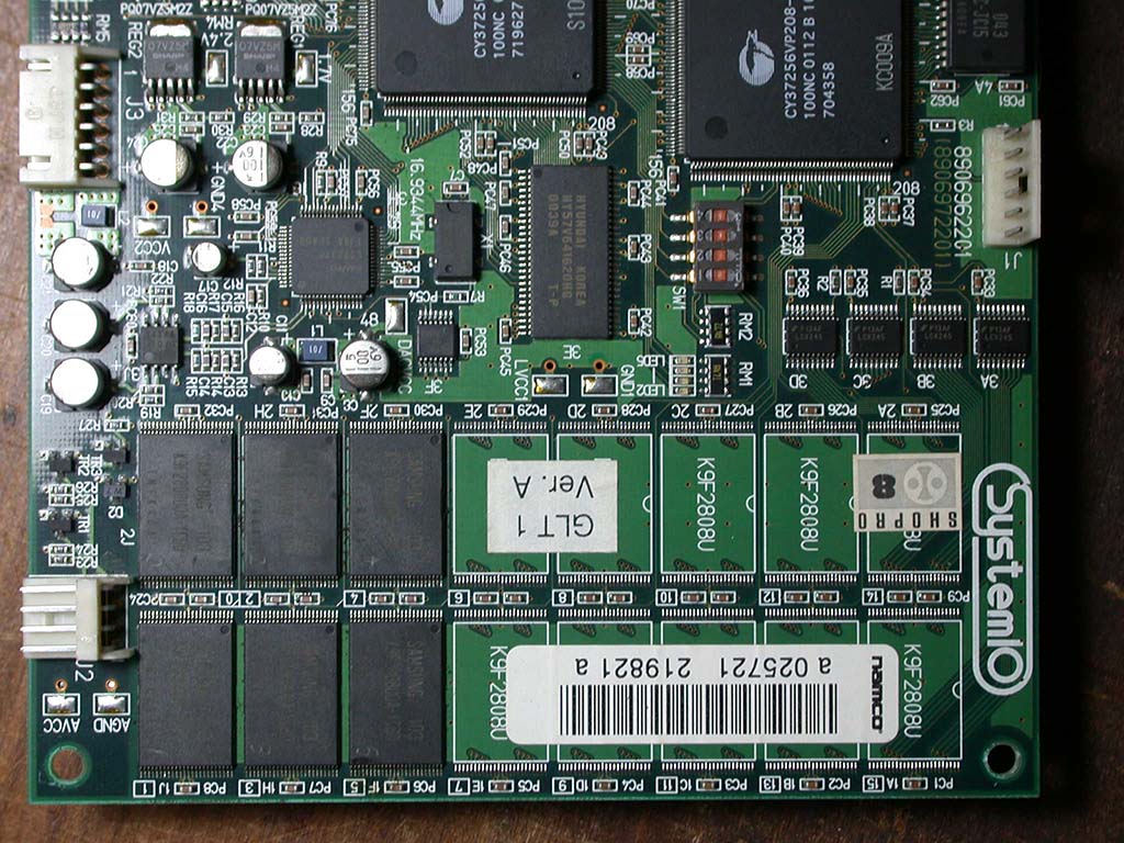
I've dumped Golgo 13 Part 3 which runs on Namco System 10 hardware.
The official title is "Golgo-13 Juusei no Chinkonka".
The English translation is "Golgo 13 The Requiem for Gunshots".
This is also crossed off as dumped on my Namco System 10/11/12 Status page
Here's some pics of the game. The last pic shows the position of the PCB in the large batch that arrived 15th July 2016....

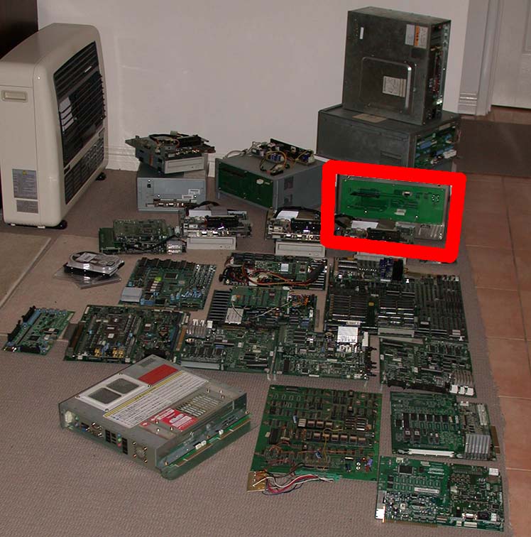
I have put the ROM dump online here. Note this will be available for a limited time until it hits MAME then you'll be able
to get it from the 'usual' places'. You can't play this in MAME and you can't use this to convert or fix your PCB. The dump is actually
useless. Due to the extreme level of encryption and protection, sadly this game and all other System 10 games will not be working in MAME
anytime soon or maybe never. Anyway, now it's officially dumped and publicly available.
5th October 2017
While repairing things over the years, I've noticed an increasing trend for arcade boards to develop faults with the mask ROMs. This problem
is getting worse and is not going to go away.
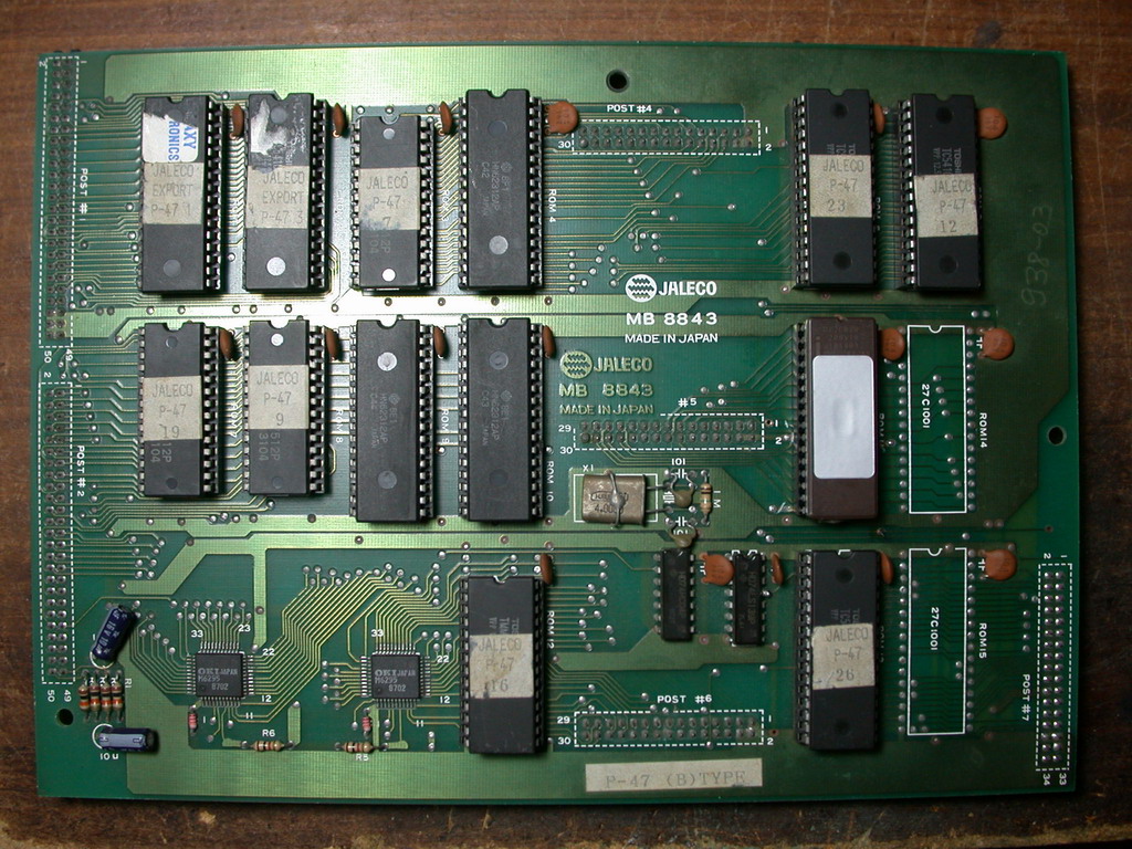
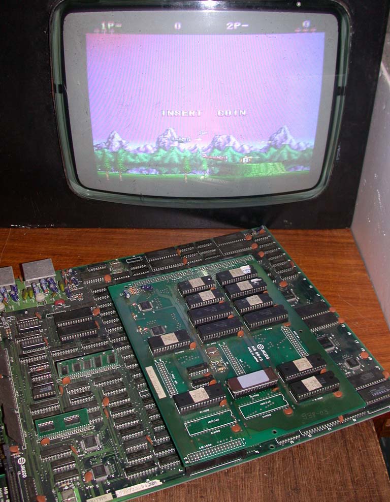
A while ago I got hold of a fairly uncommon Jaleco Megasys 1 game called P-47.
The game was working but the player and enemy sprites were missing. After a
quick analysis with a logic probe I realised the only issue was one of the mask
ROMs was dead. Normally any issue with ROMs can easily be fixed using dumps from
MAME and programmed to a common EPROM, but in this case the mask ROM was an
uncommon non-JEDEC Hitachi HN62312 mask ROM where none of the pins matched
anything else or were even close. Even power and ground were in different
places! There's virtually nothing on Google about it either.
Let's change that.... Here's the pinout.....
(2M) 256k x 8 mask ROM
        HN62312

  A8  1 +-v-+ 32  A9
  A7  2 |   | 31  A10
  A6  3 |   | 30  A11
  A5  4 |   | 29  A12
  A4  5 |   | 28  A13
  A3  6 |   | 27  A14
  A2  7 |   | 26  A15
  A1  8 |   | 25  A16
  OE  9 |   | 24  A17
 GND 10 |   | 23  NC
  CE 11 |   | 22  GND
  D0 12 |   | 21  A0
  D1 13 |   | 20  D7
  D2 14 |   | 19  D6
  D3 15 |   | 18  D5
 +5v 16 +---+ 17  D4

  CE - tied to pin 13 of 74LS139 logic chip
  OE - tied to GND
  NC - no connection. on HN62314 (512k x 8 mask ROM) this is A18
If you know anything about EPROM pinouts you will immediately see it's a pretty whacky ROM pinout!
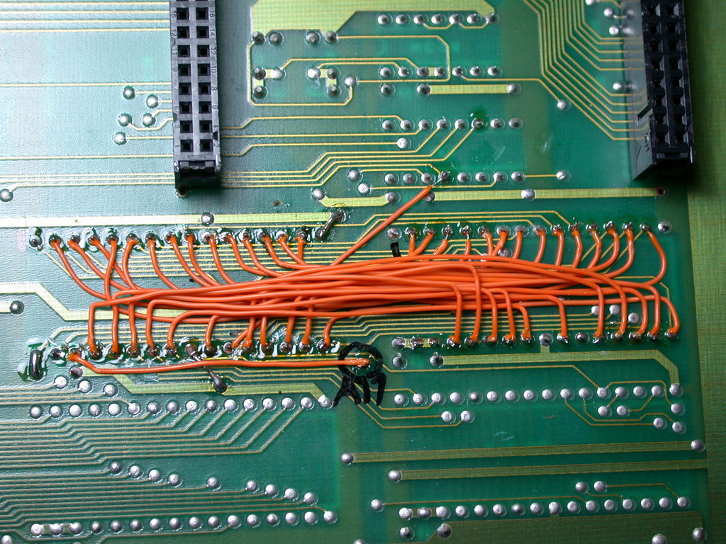
Since this is just one ROM, rather than jerk around making up a custom adapter, I decided to just get this thing fixed and modify the board
to accept a common 27C020 EPROM and move on. Then the data can be easily programmed to a common EPROM and in the event that it fails again
the EPROM can simply be changed for a new one.
The first step was to remove the socket and trace the tracks connected to the ROM. After that was recorded I cut all the tracks tied to the
ROM very neatly, soldered in a new socket and programmed the EPROM with the data from MAME. Well almost. These larger 2M-bit mask ROMs
contain data that is identical to the already dumped 1M-bit version EPROMs. The 2M-bit mask ROMs were dumped some time ago but unfortunately
someone didn't think it was important enough to document it in the source code so the 2M-bit mask ROM dumps don't exist. Considering MAME's
main goal is to document the history of arcade games, the fact that this anomaly has not been documented is somewhat disturbing! Makes me
wonder what other valuable info has been brushed aside as unwanted by some dev who knows nothing about real hardware and PCB repairs.
Hmmmm.....
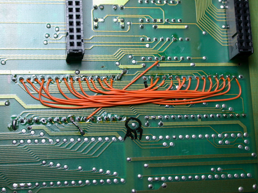
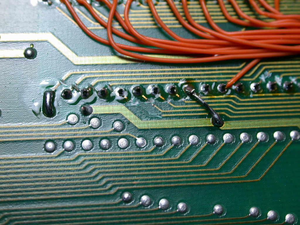
Anyway, the next step was to carefully wire each pin to the circuit. In the end it was actually pretty easy. Almost all of the tracks are
common with a 27C010 EPROM next to it. The highest address line A17 goes off to the connector 'POST#7' directly (A17 is not on 27C010) and
CE goes to a logic chip. OE was just hard-wired to ground. So I got to work wiring it and after about 1 hour it was done. Conveniently the
power and ground pins were close to normal power and ground locations so I just jumped them using a wire jumper and solder. Now it works
great! Apart from a sticker on the top of the EPROM, from the top it looks all original and is now a lot more reliable with common EPROMs
instead of crappy old mask ROMs :-)
It may look a bit rough from the bottom side but it is not seen when assembled and the main point is
it was fixed quickly and now works 100%, rather than being just another broken piece of crap piled up in my garage ;-)
This board has been added to my Items For Sale page which now has 3 racks :-)




26th June 2017
Occasionally something comes along that is so incredibly rare and obscure that no one has a clue what it is and it gets passed by totally
unnoticed by everyone. Everyone except me, of course ;-)
That happened last year when I picked up a rare Namco game called "Abnormal Check".
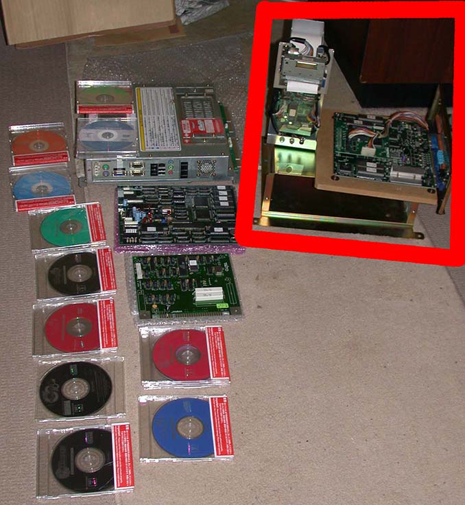
The basic hardware is Namco ND-1, but with an extra daughter-board on top that controls a printer which dispenses a print-out at the end of the
game. I had to tie a few printer status signals high/low to get it to boot up but after that the printer is ignored so it's playable. The game is
entirely in Japanese but can be played by randomly hitting buttons when responding to the questions (or you can learn Japanese hehe!)
In a multi-player game, there's some hilarious effects when the player dies, including the head getting cut off and flying into the air, stomach
opening up and bullets coming out shooting the losing player, lightning bolts frying the losing player, turning old and grey etc.
At the end of the game the winner is put into the spotlight and grows 2X bigger.
Here's a few pics from the game, including some hardware shots at the end. The last hardware pic is from the previous post showing the placement
of this item in the pic. The thermal printer is sitting on top of the metal box to the left.
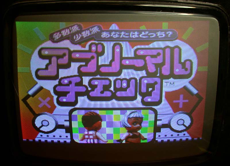

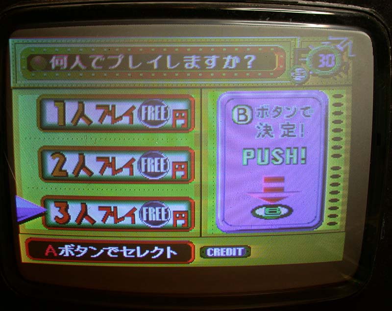

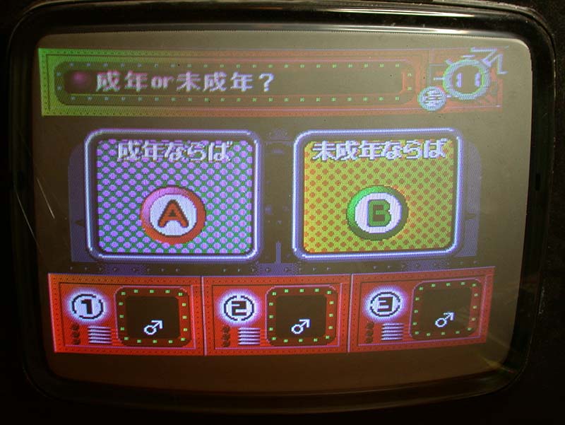

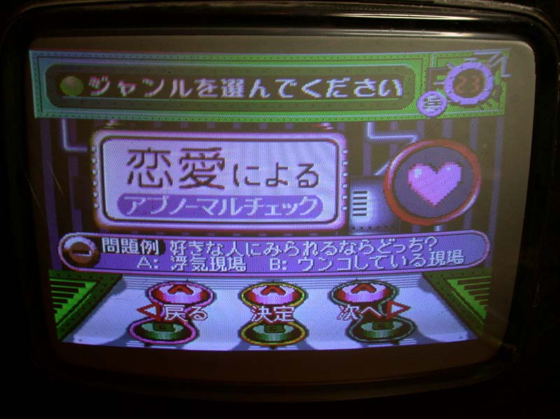


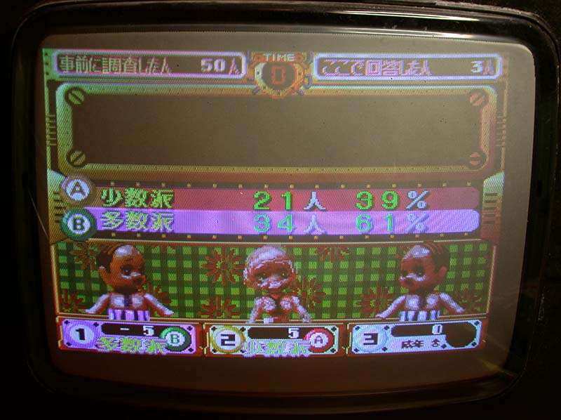

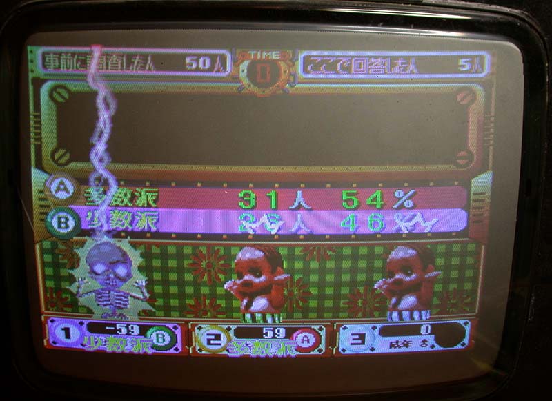

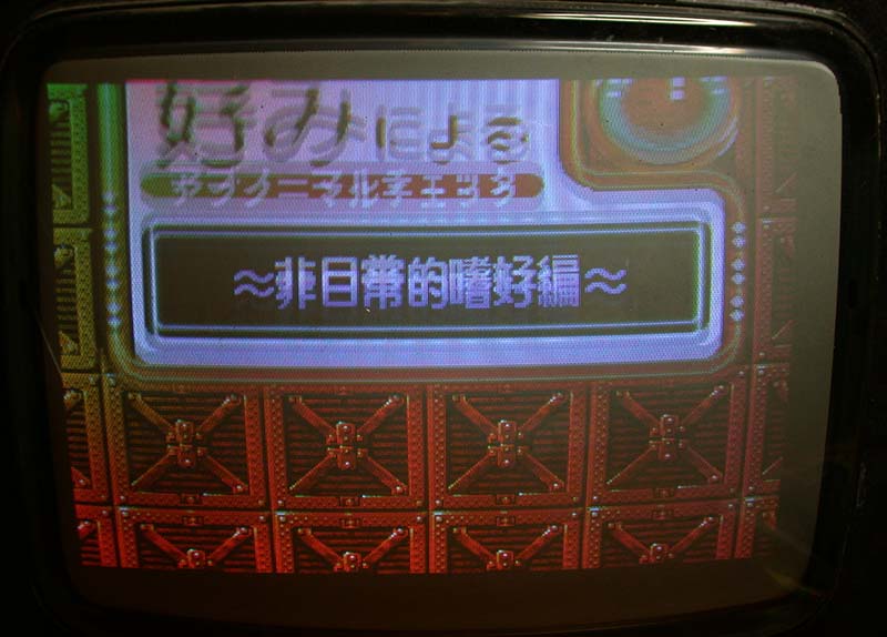
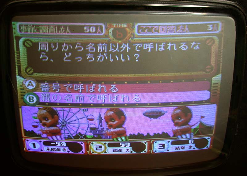
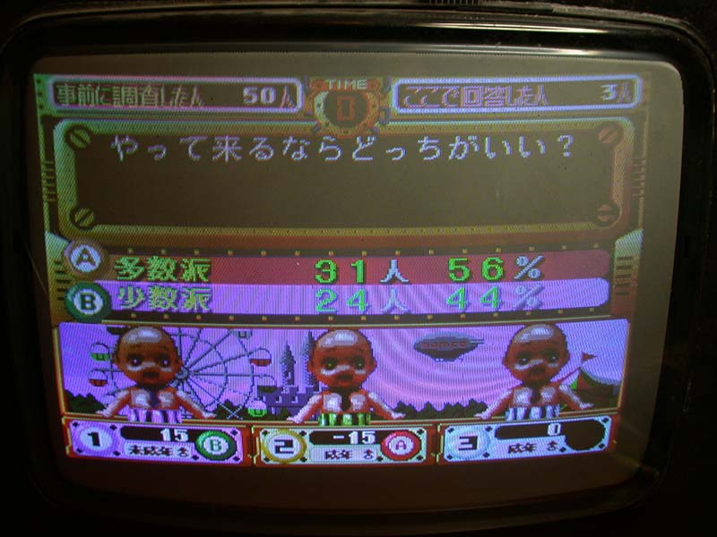

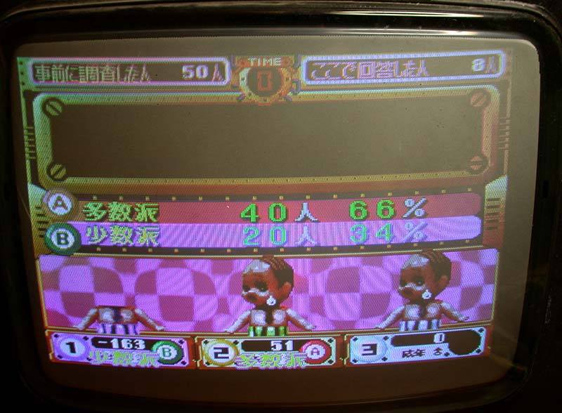
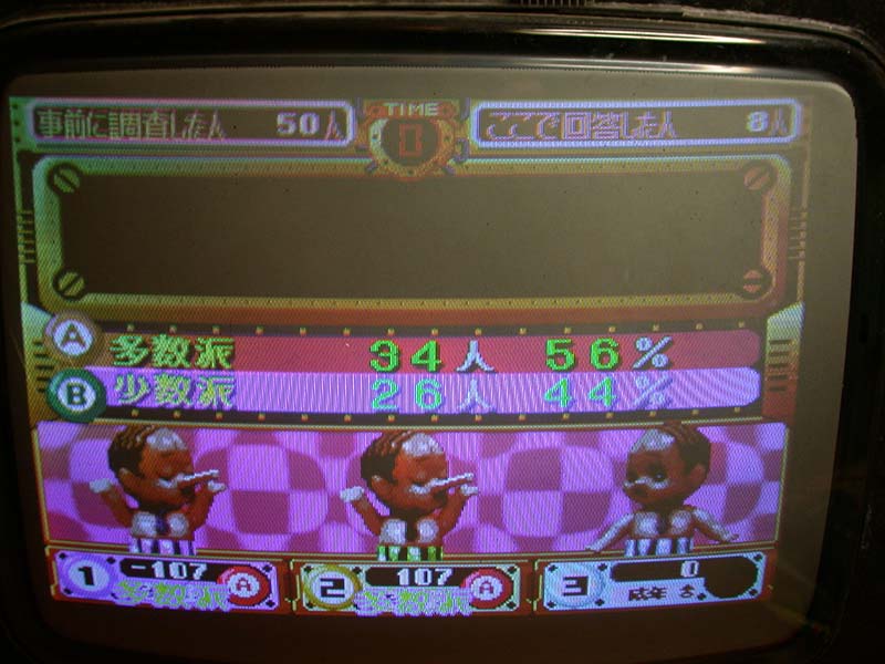

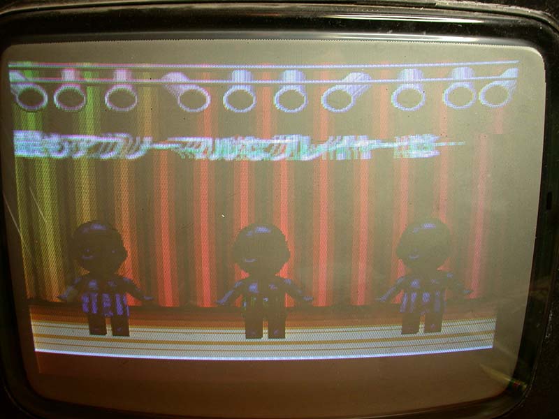
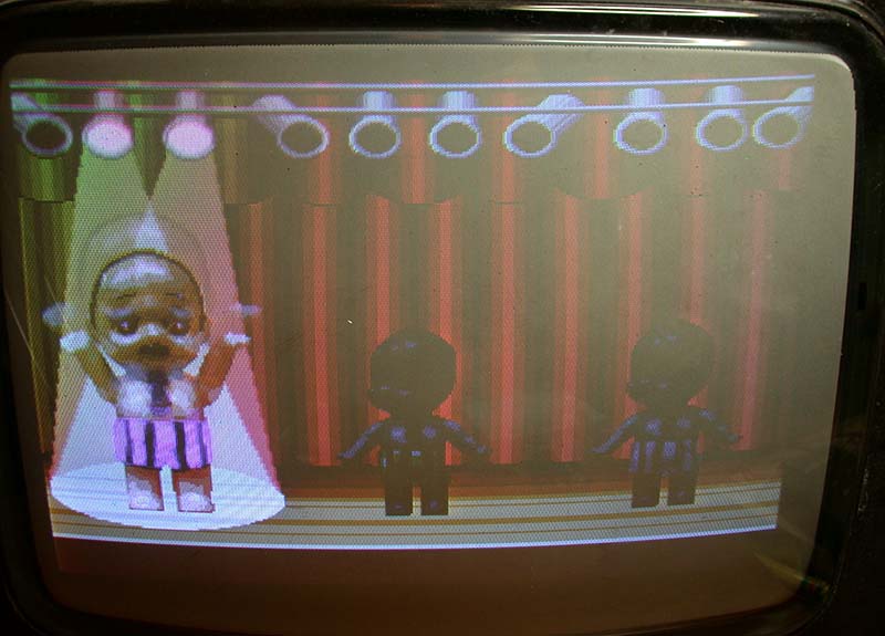

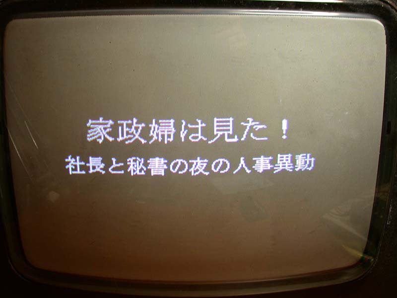


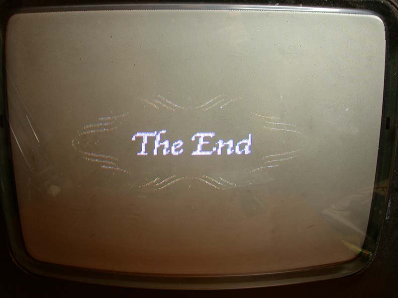


And here's a shot of the title screen from the emulation, thanks to R. Belmont.

There's no additional pics to show of the emulation because in general the ND-1 driver in MAME isn't complete enough to allow it to just run.
The original ND-1 driver in MAME is very hacky and minimalistic and there are some serious graphical issues due to incorrect/incomplete emulation
of the Yamaha YGV608 graphics chip. Abnormal Check is using the chip in different ways and exposes a bit more about how the chip
works so hopefully it gets fixed in time. As a result of that, Namco Classics 1 and Namco Classics 2 should also improve :-)
15th June 2017
Some more undumped PCBs from Japan arrived a couple of days ago....
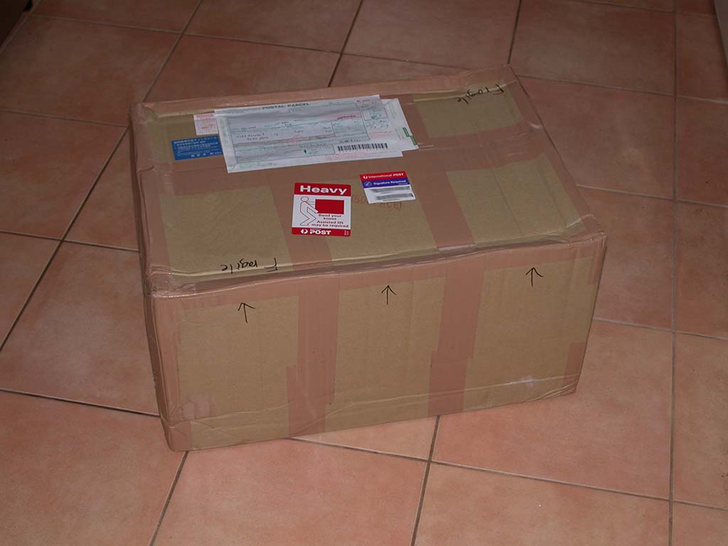

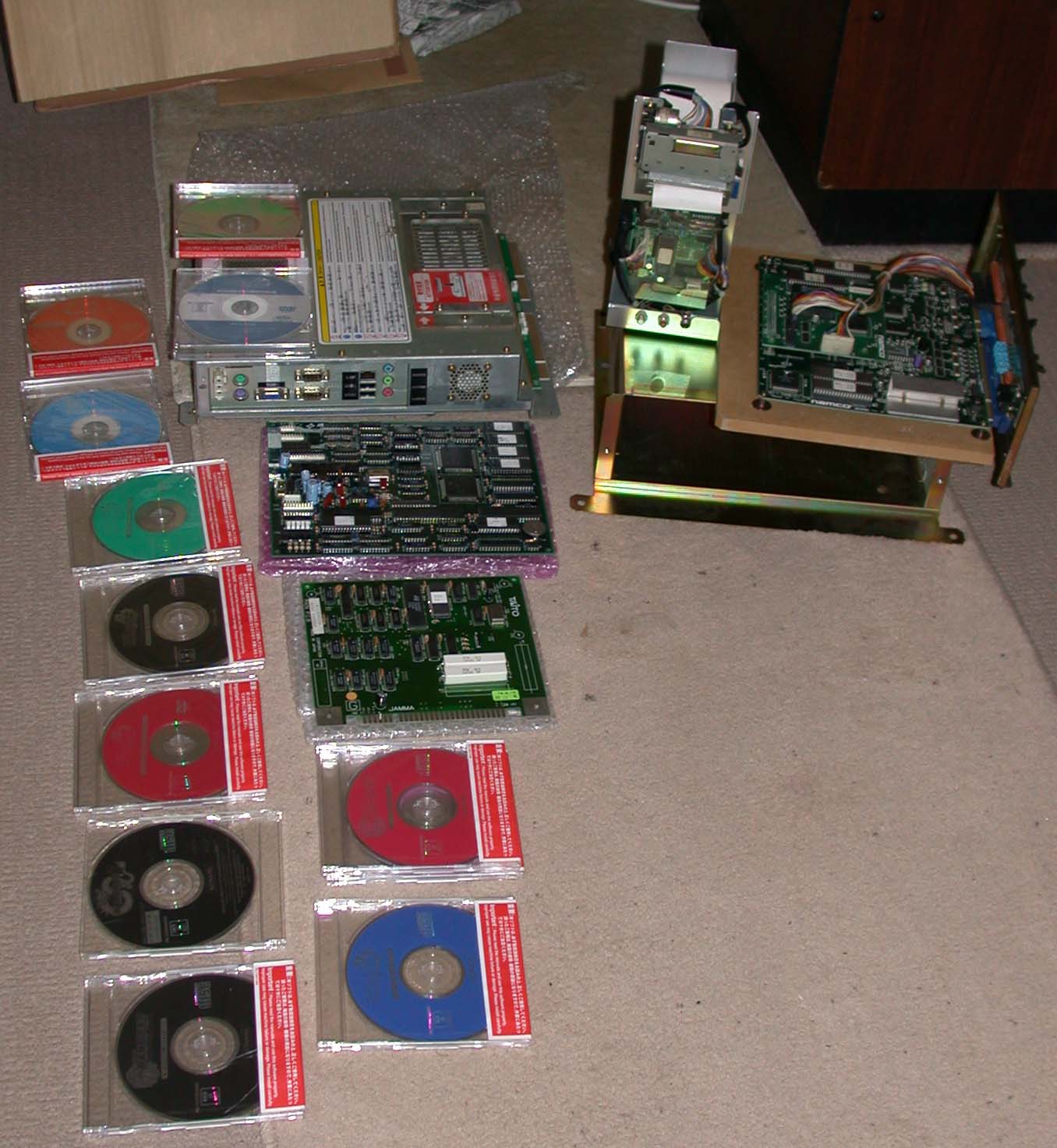
All these are extremely rare and not dumped. One is another Konami Viper/PC server with 12 CDs/DVDs (there was a similar but not identical one
in a previous shipment), a small Konami PCB which is super ultra rare, and an ultra ultra super ultra rare Namco game running on Namco ND-1 hardware
that was previously thought to be just a myth.
There were also two free PCBs. One is a Taito Mini Vaders PCB which is working fine.
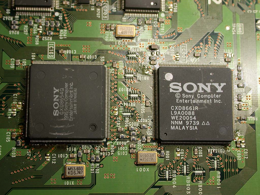
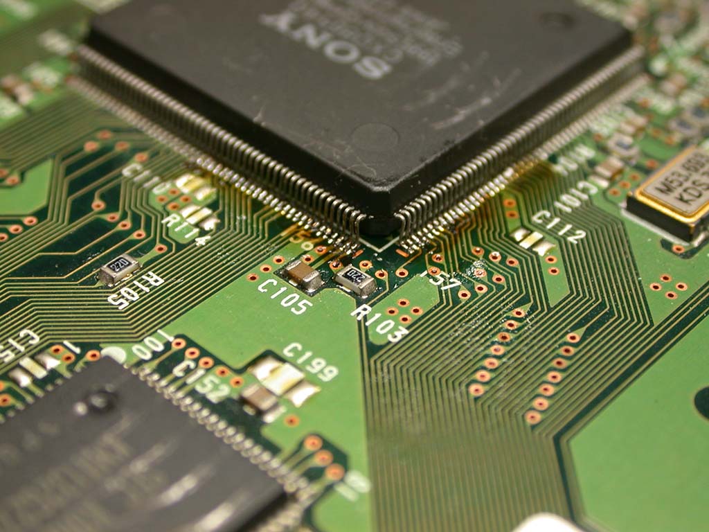
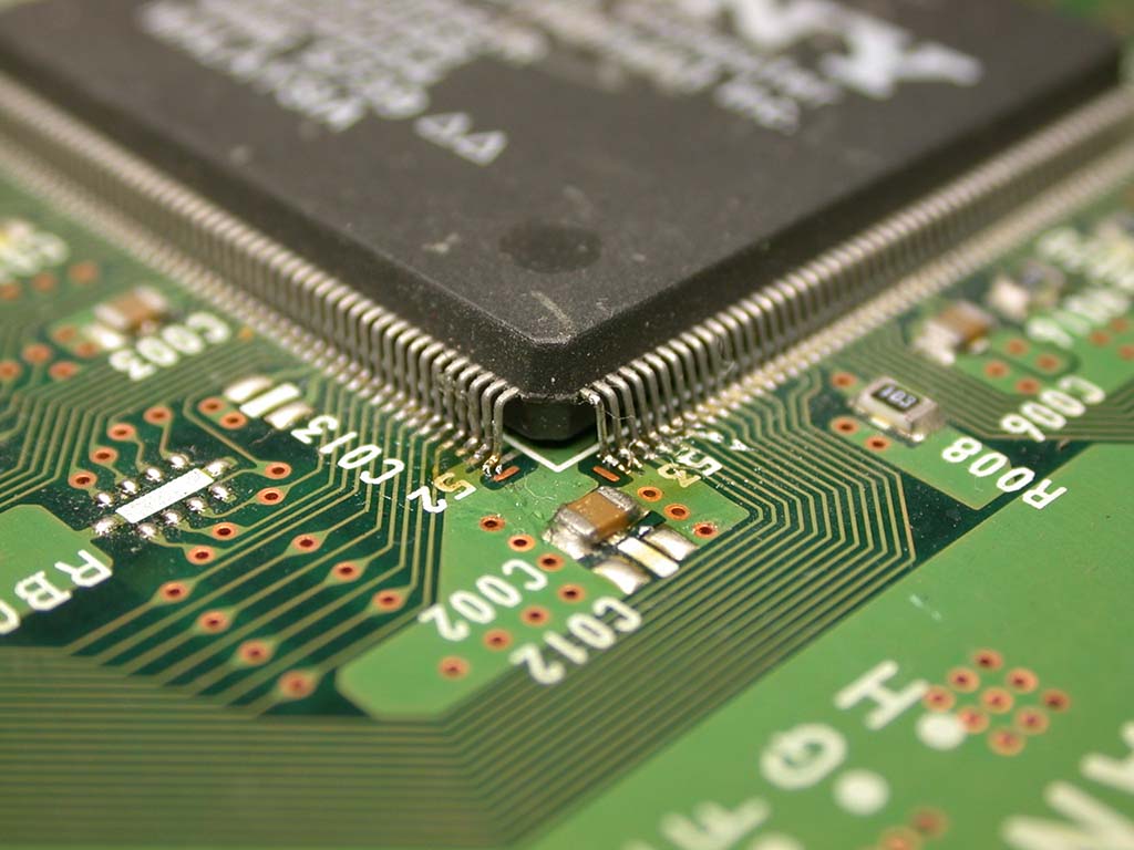
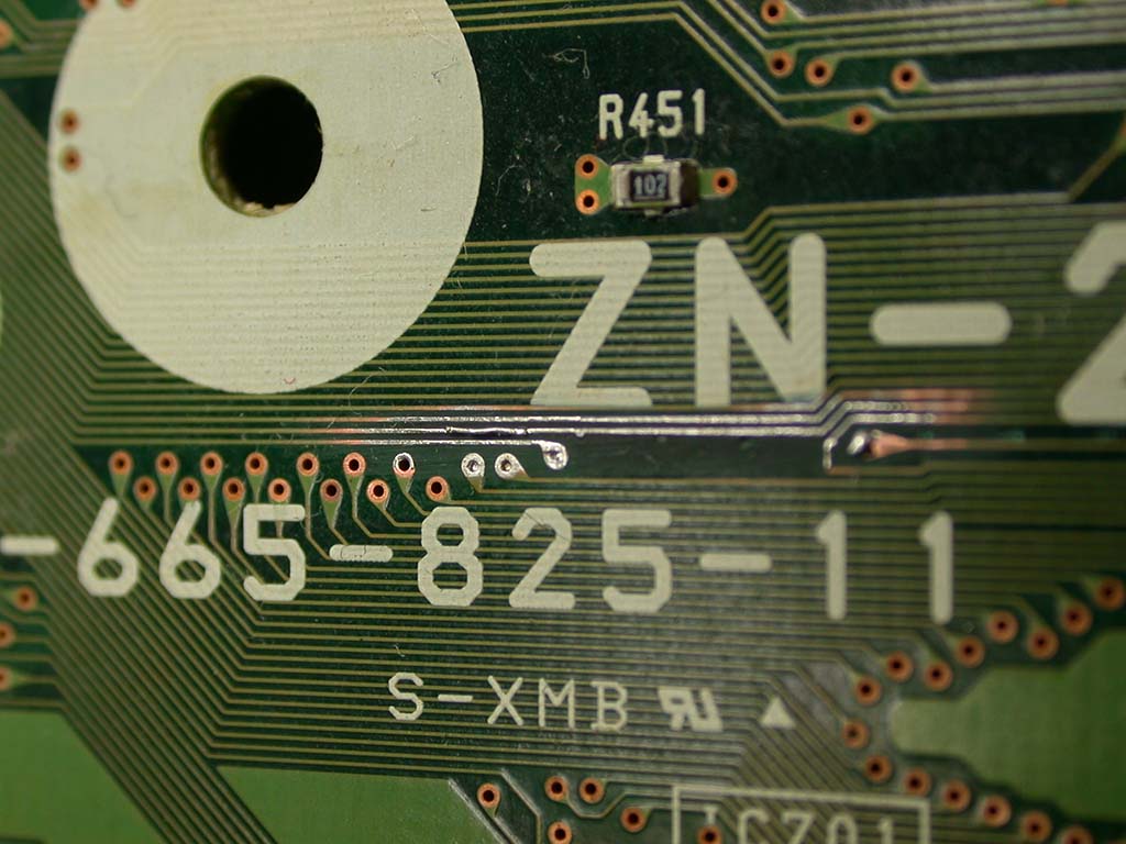
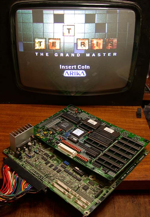
The other is a Tetris The Grand Master PCB (already dumped version JAPAN 980710) that was not working. There were some loose chips on the lower
ZN2 PCB and a broken track which seems to have been caused by some other PCB being pushed hard against the chips on the lower PCB. That would be
impossible while the top PCB was plugged in so at some point it died and was dissassembled and then not stored well after. The actual real fault
was loose legs on the large Sony chips but the additional broken track done at a later time meant that even if the original fault was fixed it
still would not have worked. Regardless of the damage, the actual PCB is in very nice condition with only minor scratches on the top of a few
large chips. The under-side of the PCB is like new. I repaired the faults in about half an hour and now it works just fine :-)
I also recently did some Namco System 246 dongle cart conversions and one of the supplied carts was an alternative version of Tekken 5 Dark Ressurrection which is not
dumped so I dumped it.
8th May 2017
Anyone with a Konami PCB from the early to mid 90's will know about the dreaded KONAMI 054986A black ceramic module that develops issues and
causes the board to either fail to boot-up or the sound is missing completely. The module is used on Lethal Enforcers, GI Joe, Violent Storm and many others. Usually it can be resolved by
changing all of the capacitors, but sometimes the leaking caps cause damage to the fragile circuit. In the past there have been some fairly weak
efforts to draw that circuit, but in all cases it was limited to the simple parts on the top side of the module.
If you saw those poor diagrams and thought it would be nice to have a full schematic of the entire module, today is your lucky day.

1st May 2017
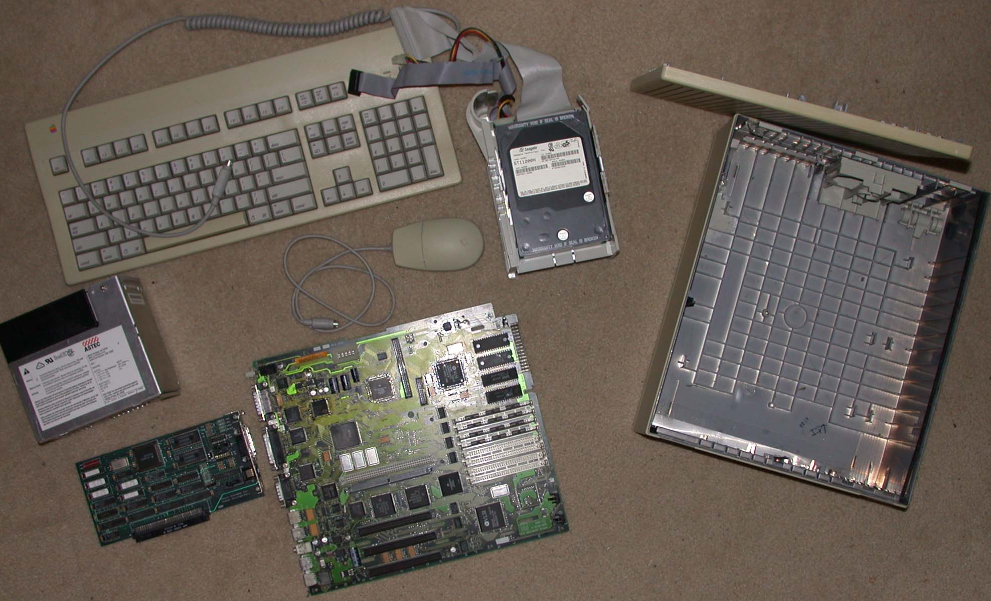
It's time the non-working Apple Macintosh IICi moved onto a new home. If you are looking for bits and pieces for a IICi I am stripping it and selling
off the parts, or you can buy the whole thing as-is if you want.
Check my For Sale page here for pics and info of what is on offer.
In other news, another chip just got decapped and dumped by CAPS0ff. This time #145
7th April 2017
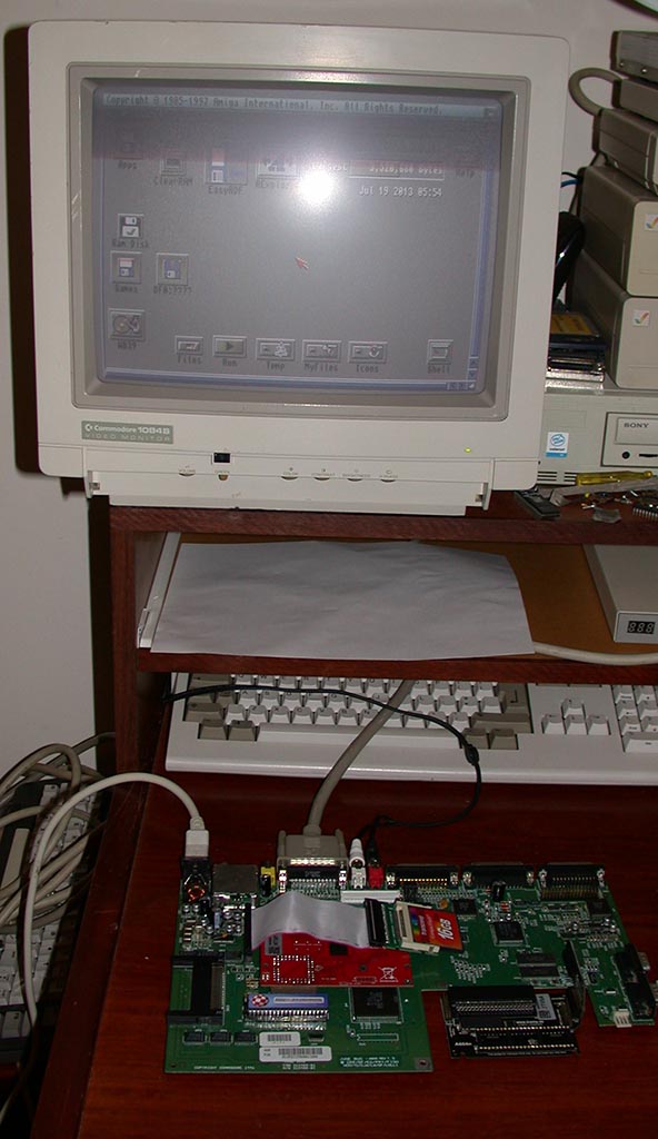
Another Commodore repair job came in today. This time we have an Amiga 600. There is an Individual Computers ACA620EC 68EC020 accelerator card
fitted over the top of the PLCC 68000 CPU which seems to be flakey. Sometimes it works, sometimes not. Most of the time it starts to boot then
gives some checksum errors then crashes. Re-seating it several times helped but even then sometimes it still crashed randomly.
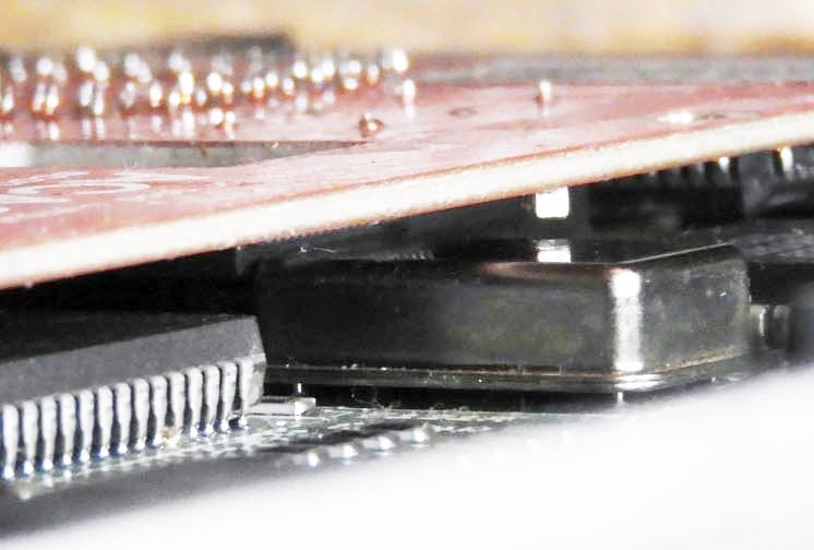
After a closer inspection I noticed the card isn't sitting fully down on one side and looking closer reveals the 68EC020 is fouling on top of
the 28.375MHz oscillator on the motherboard. Maybe just on the very edge of the radius on top of the oscillator tin can.


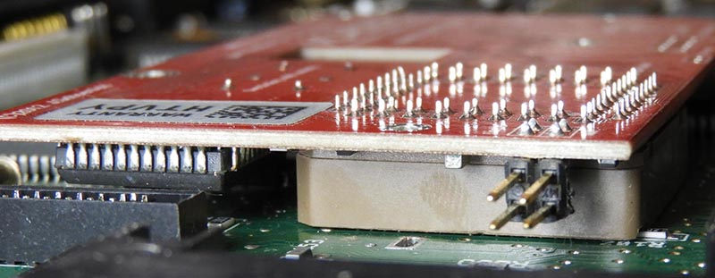
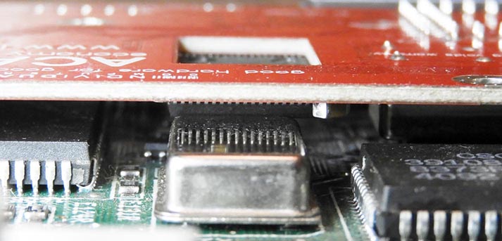
This is a bit unusual because this card is specifically designed to clear and fit properly within the constraints of the A600 motherboard and I
found no reports of this problem with a quick google search.
I figured I'd start by removing the PLCC socket and have a closer look. I was thinking maybe I could lift up the PCB slightly and then it would
clear (it would have an air gap under the socket) then re-solder it in place and it would clear. With the socket removed, I fully pushed the PLCC
socket down onto the 68000 CPU and it went down all the way with a 'crack' sound... meaning it's now on very tight. I don't think the socket has ever been on that tight.


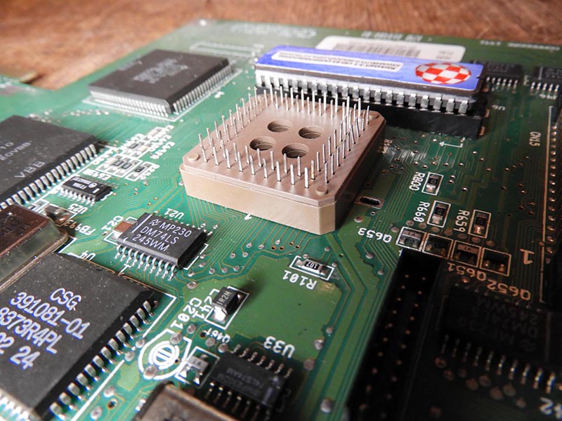
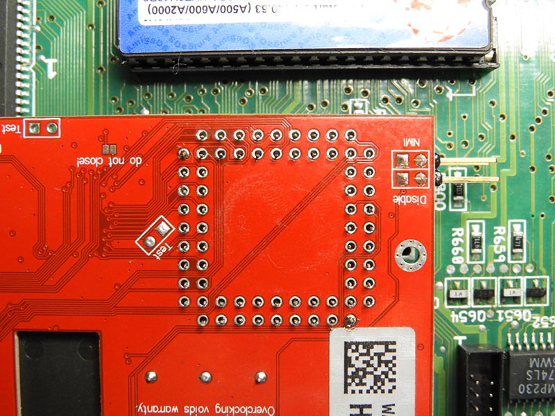
So then I put the PCB back on top of the PLCC socket, just sitting there loosely and noticed the 68EC020 CPU was no longer hitting the top of the
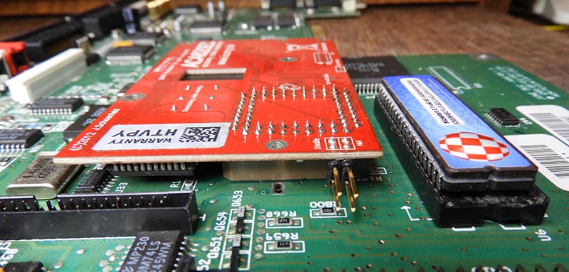
oscillator! There is some movement between the pins of the socket and the holes on the PCB and I can take advantage of that. When pushed up (away
from the oscillator) the 68EC020 clears and the board is fully seated. So I tacked it in place on two pins to test the theory and sure enough it
no longer fouls on the top of the oscillator. So all that's left to do is simply solder it back in place. Basically it just needed to be
re-positioned about 1mm so it cleared. I did a quick test after and now it's working perfectly :-)

I'm still looking for other random Amiga power supplies to make schematics and some parts from a not-working 1084S monitor as per the post below.
If anyone wants to assist please contact me. See the post below for the details.
13th March 2017
I've been busy over the last 3-4 weeks doing a lot of Commodore repairs that came in.
Here's a quick run down of the problems and what was done.
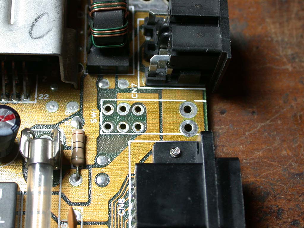
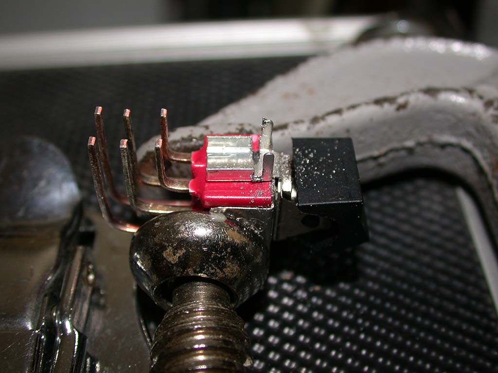
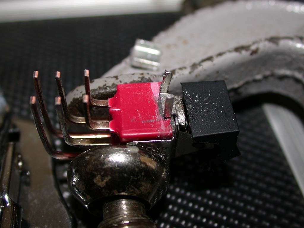
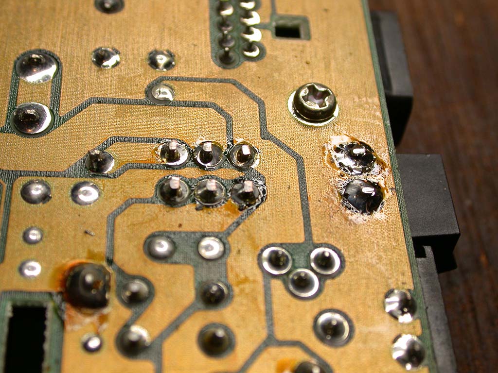
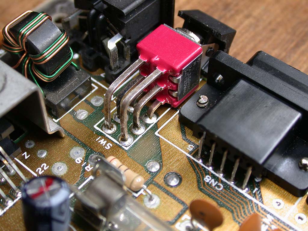
Commodore 64 faulty power switch repair
Very common problem, the switch works sometimes and sometimes not. Easy to fix, just replace the switch. Problem is we're about 30 years too late
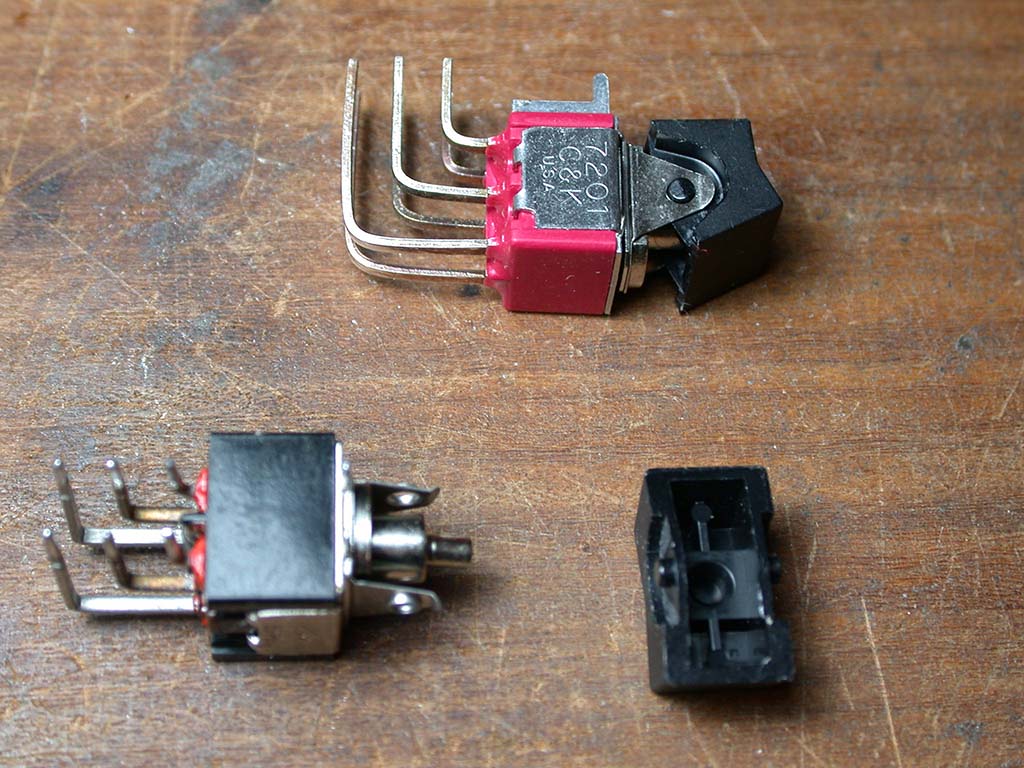
to buy the parts now. I found a similar switch online and bought it hoping it would be a simple drop-in replacement. It almost is, but the plastic rocker
was too big. Luckily the design is similar and the plastic rocker can be swapped with the original one and fits ok. So I swapped
everything over, inserted the switch into the PCB then errr, it didn't push down fully. I got out my trusty hacksaw and chopped off the bottom part
of the bracket which isn't needed anyway and now it fits perfect. Soldered it in and it's working fine.

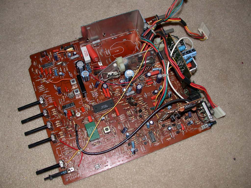
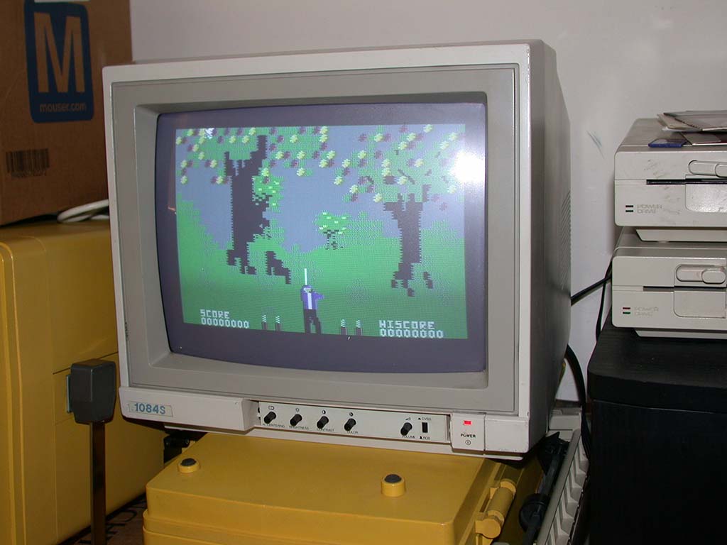
Commodore 1084S-P monitor repair
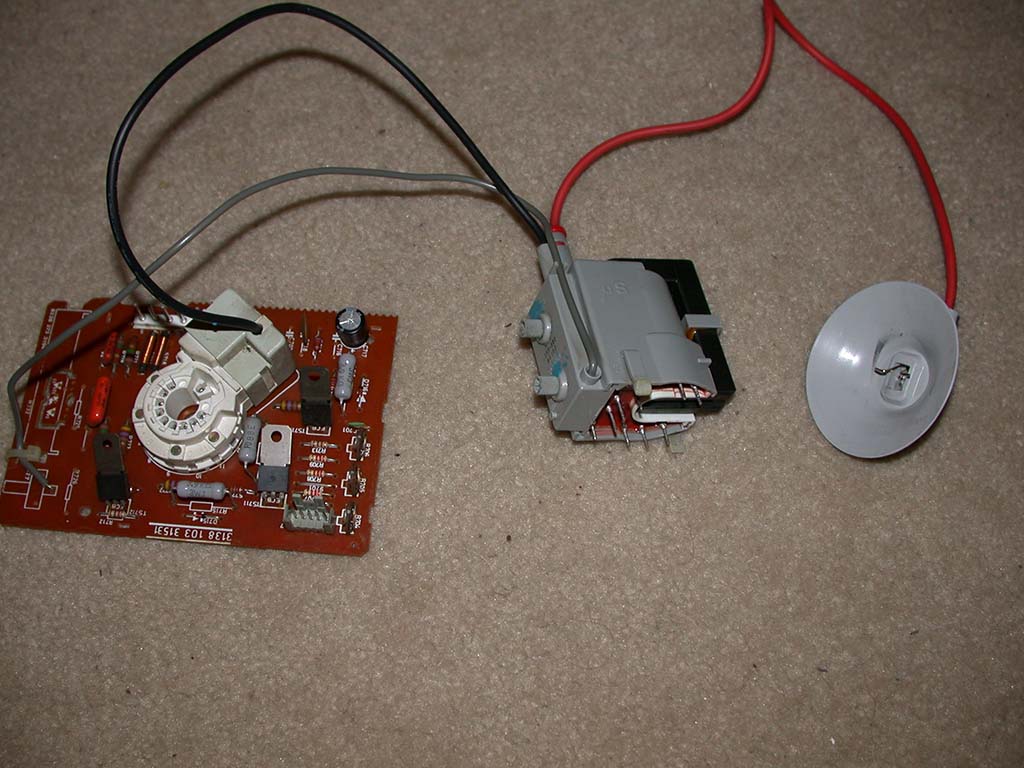
It was just making a whining sound and the power light was off. That's a classic sign of an internally shorted flyback. Luckily, replacement
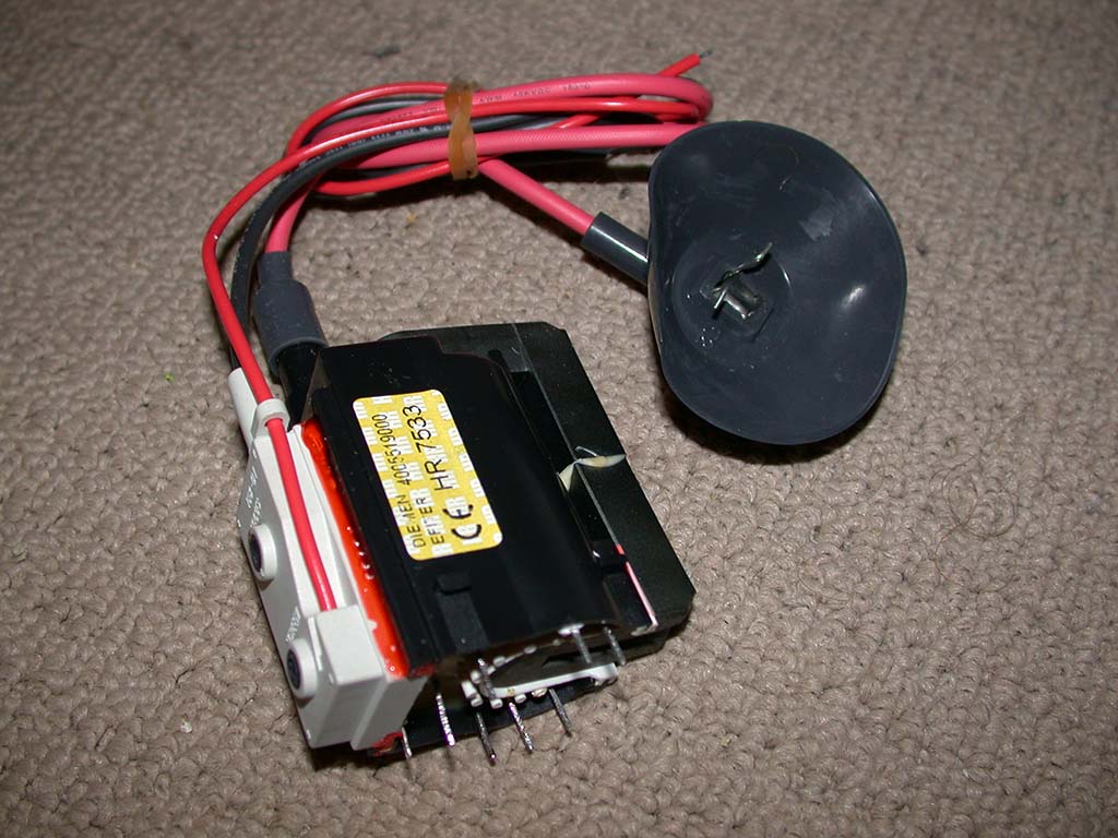
reverse-engineered flybacks for *some* monitors are still available from a company called HRDiemen. I pulled the flyback out, ordered a new
one from a local distributer, soldered it back in, adjusted all the various potentiometers etc and it's working just fine now. One word of
caution regarding these replacement flybacks, I have bought many of them over the years and every one has been shipped with the screen
control pot turned up full. That basically over-volts the neck board and tube RGB guns by 2 to 3 times and can blow up the neck board or
tube or both. If you fit one of these new flybacks, be sure to turn the screen control pot all the way down (maximum turn counter-clockwise)
then adjust it as required.

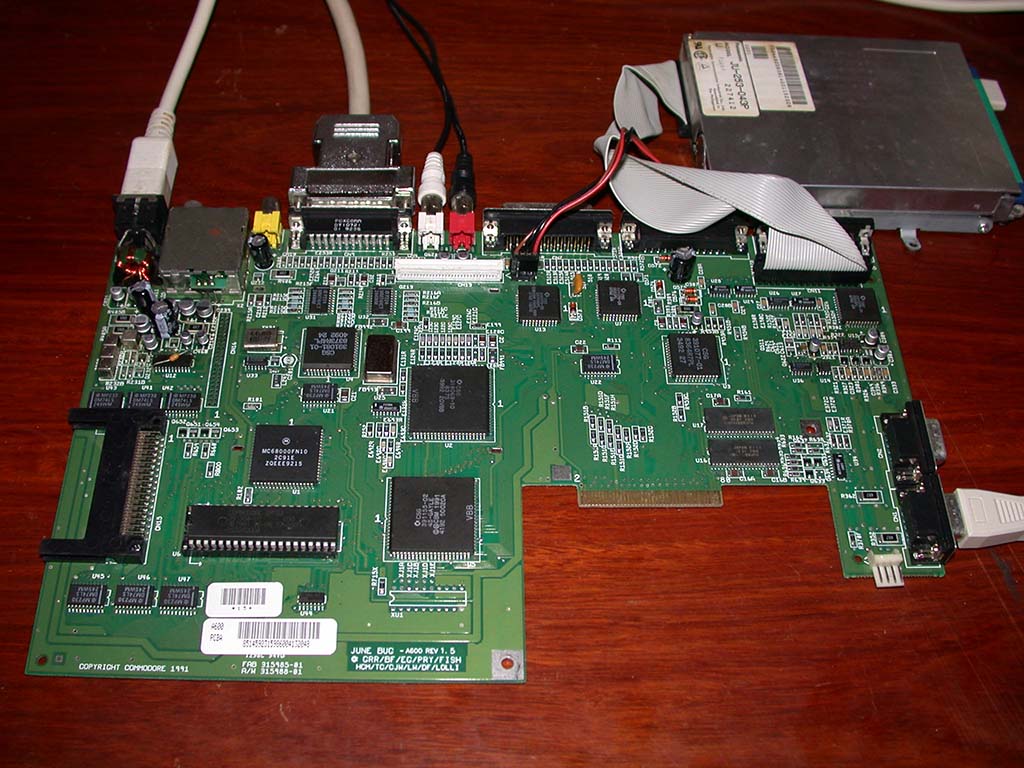
Commodore Amiga 600 repair (and rant about caps)
This had a fault where it would take about 10 minutes to power on. After that it would work fine until powered off, where it would then take
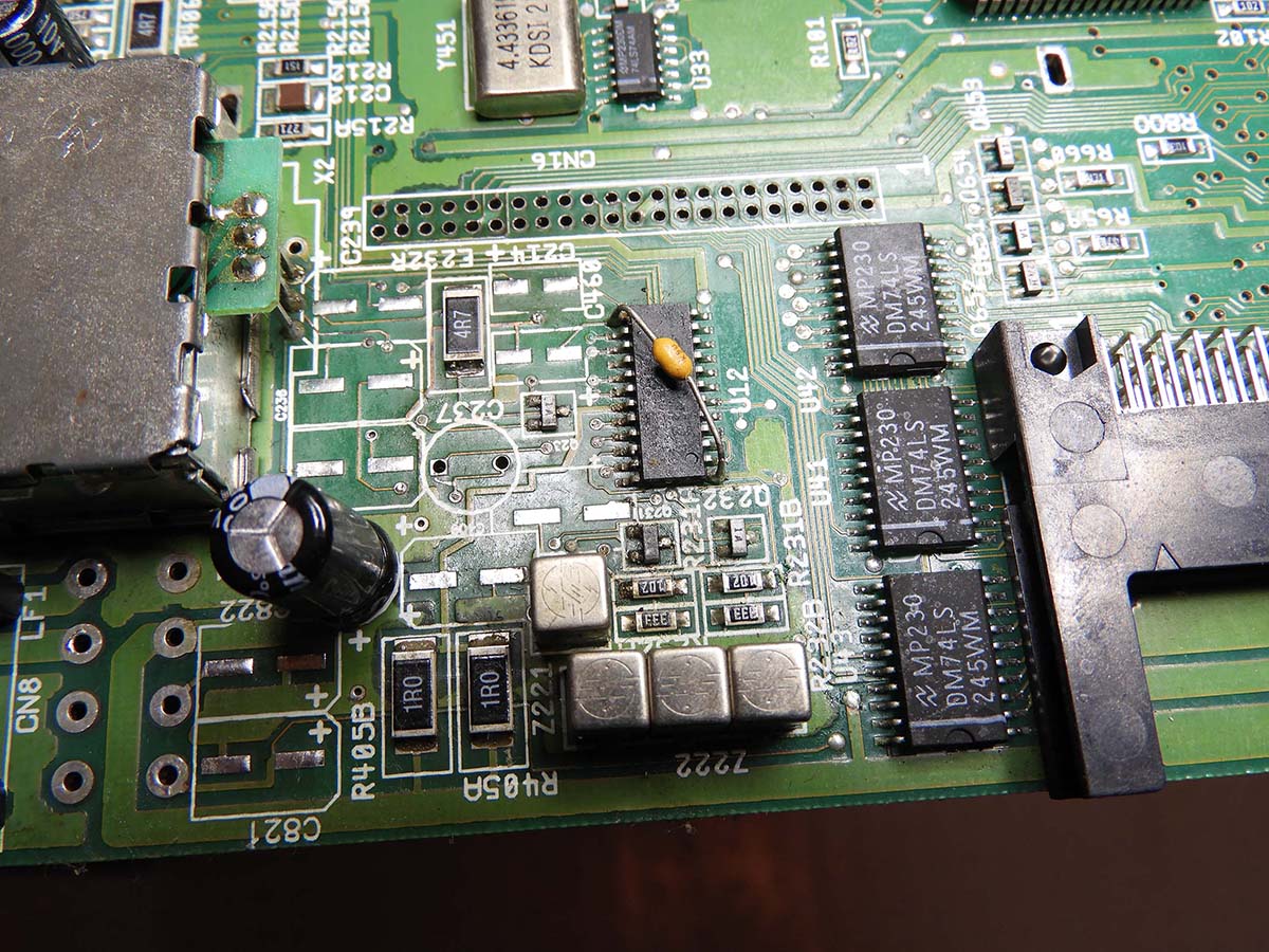
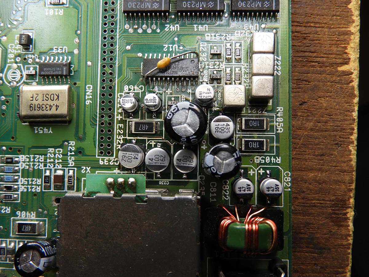
another 10 minutes to boot-up again. That usually means bad capacitors. Sure enough when looking around there was leaky caps in the reset
section and some corrosion. When it did work the sound was strange too. If you check the first photo (below) you can see the crud build-up on
the SMD op-amp chip, which explains at least part of the sound issue (more on that later). First thing to do is remove all the effected
parts, then clean up the PCB, check for track damage (there wasn't any) then replace all the parts with new parts. The owner had previously
bought a cap kit from a popular Amiga part supplier in UK (ending in 'kit') but was not confident enough to do the job himself so he
provided that to me so I could swap over all the caps. I replaced the first two bad caps in the effected area and the other things such as
SMD resistors/caps/transistors etc and the op-amp IC, powered on but that didn't fix the booting issue. The sound issue appeared to be
slightly better but still not right. I then consulted the schematic and found that the section that was damaged is actually the
amplification circuit. Well at least that should be fixed now hehe! The reset IC (LM555) is tied to a smaller electrolytic 10uf cap so I
changed that and it vastly improved the power-on time from 10 minutes to about 1 minute. An improvement sure, but not good enough! The Amiga
should of course power on instantly. When it was working, I also noticed the sound on the left side of the monitor was lower in volume than
the other side. That is generally a cap problem too with the caps connected to the outputs near the RCA jacks. So then I proceeded to
replace the remaining caps on the board since I had the cap kit anyway. After replacing all the electrolytic caps I noticed the sound
problem was solved but the computer was still not booting up immediately like it should be doing. It also sometimes would not see the HDD. I
checked the 44-pin HDD connector and found a couple of loose pins. The connector was damaged so I have ordered one to replace it (currently
waiting for it to arrive). With my logic probe I could see the output on the reset chip was not firing. I checked the schematic again and
noted there are a number of SMD parts in the reset section connected to the 555 timer, located on the top side and bottom side of the
PCB.
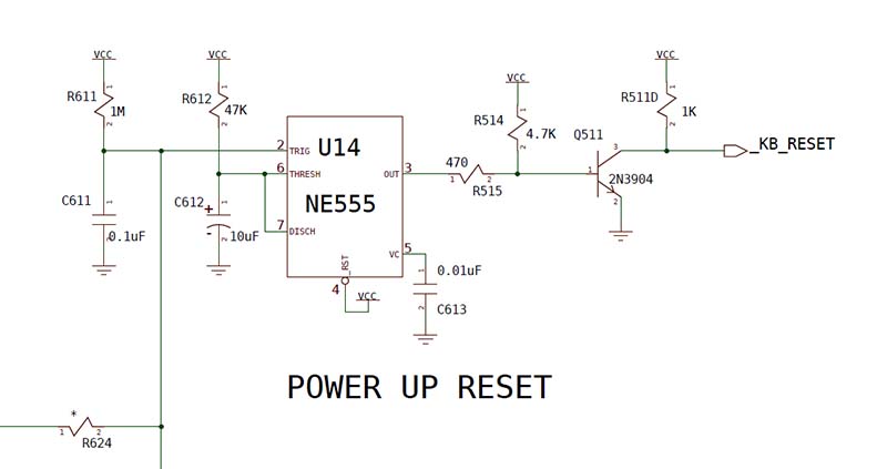
I pulled each part and tested them and they were all OK. The only part I had not checked was the "new" 10uf electrolytic cap at
location C612 that I had replaced from the cap kit. So I pulled the cap and tested it and found it to have an ESR reading of 4.2ohms. That
is WAY too high for a cap in the reset section, about 3-4 times out-of-spec for the 10uf 35v cap which was supplied. I grabbed a quality
Matsushita/Panasonic high temp low ESR "FR" range cap from my spare parts stock (which is basically the highest specification cap available
from that company), swapped that over then powered on and BAM! it powered on immediately. Problem solved! So the moral of this story is use
only low ESR caps in the reset section and beware of companies/people who sell cheap cap kits. Cheap as in "cheap caps", not cheap as in
"cheap price". The cap kit provided was certainly not a cheap price but the caps are definitely cheap Chinese crap caps. Always buy quality
Japanese electrolytic caps when working on repairs of expensive or uncommon electronics, otherwise you'll be sorry. There are really only a
few that are guaranteed for 10+ years and they are all made in Japan. Most of them will last 30+ years. They are made by Nichicon, United
Chemi-con, Matsushita/Panasonic, Rubycon and a few others. If you are interested, you can google 'bad caps' and read all about cheap
rubbishy caps that have become famous on sites like badcaps.net so you can avoid them! Unfortunately that site now requires an account to
view forum posts so I can't recommend it. There is another site that has a full list of every brand with photos and info at
http://capacitor.web.fc2.com. This site allows you to identify the brand of any cap (including cheap caps). The site is in Japanese but you
can use google translate or the Chrome browser to auto-translate it. The site is *very* informative so it is worth the effort to do some
research there.
Do yourself a favor, when buying electrolytic caps for quality electronic equipment, only get them from official channels like Mouser,
Digikey, Element14, RS etc and choose the quality Japanese brands (they usually sell several other brands too). You will also save money
because other companies and sellers just buy them from places like that (usually selecting the cheapest brand they can get away with), mark
them up and re-sell them for a profit. Otherwise you're probably buying cheap Chinese caps that will fail in a year or two and possibly
damage your rare collectable equipment. Those companies and individuals are only there to make money and will do whatever it takes to save a
few bucks. To give you an idea, a cheap cap costs 10c, the good quality version costs 65c. That's a difference of 55c. That may not sound
like much to you and me, but in quantites of 1000 it's an extra $550, and of course they are there to make money so they cheap out and use
crappy caps. Don't buy them from eBay either because the Chinese cap companies have copied all of the brands and sell them as genuine good
caps when in fact they are cheap copies with the same branding marks!
If you do want to buy a cap kit ask the seller what brand caps it has. If they are reluctant to tell you or they don't know or they just say
they are using the best quality caps available, it's almost certain they are using cheap caps. If you have caps already and want to know if
your cap is good use an ESR meter to test it (available on ebay for a small price), then refer to the standard ESR charts floating around
the net to see if the cap is good or bad. The uF reading should be within +-5% of the number printed on the capacitor and the ESR should be
within the specification on the chart. The actual ESR depends on the voltage rating of the capactitor and the uF so you need to refer to the
chart to know if it's good or bad. Only use caps within specification and toss out-of-spec caps in the bin where they belong. The Amiga
deserves only the best and only Amiga makes it possible!


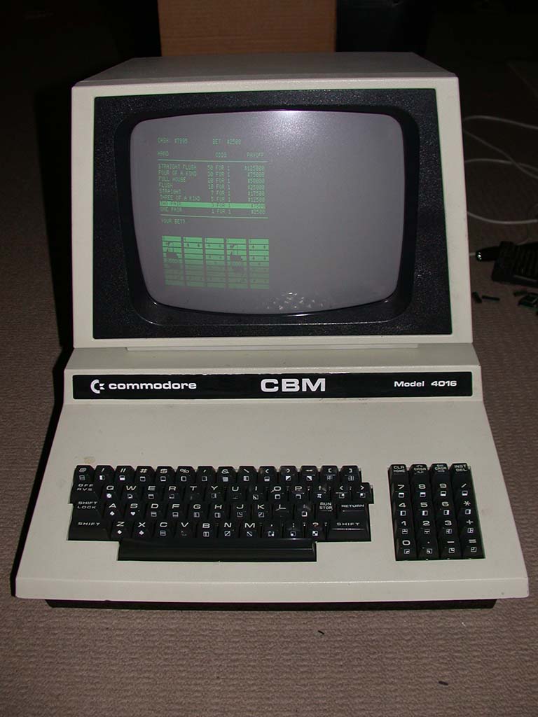
Commodore CBM 4016 repair
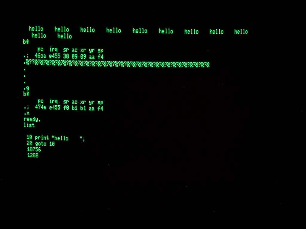
This one took a few weeks to figure out. It would boot up and work, but then lock up at some random time. Sometimes it would run for 3
minutes, or 30 minutes, or 3 hours. If I powered off then on it would work again perfectly for some random amount of time. Sometimes when it
crashed it would drop out to the built-in machine code monitor. Other times while running a simple basic program it would stop with a
"syntax error" and just one character had been changed to a 4x4 checkerboard pattern symbol. After fixing the error in the program it would run again until
it crashed again later. It was crazy! When it ran long enough to run a software RAM test, it didn't find any errors. The voltages were ok so
it wasn't a power supply issue. The board was really gross too. Some idiot had sprayed silicon spray all over the board and it was a really
nasty slippery slimy thing to work on.
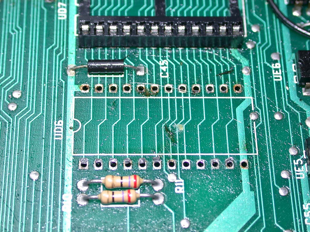
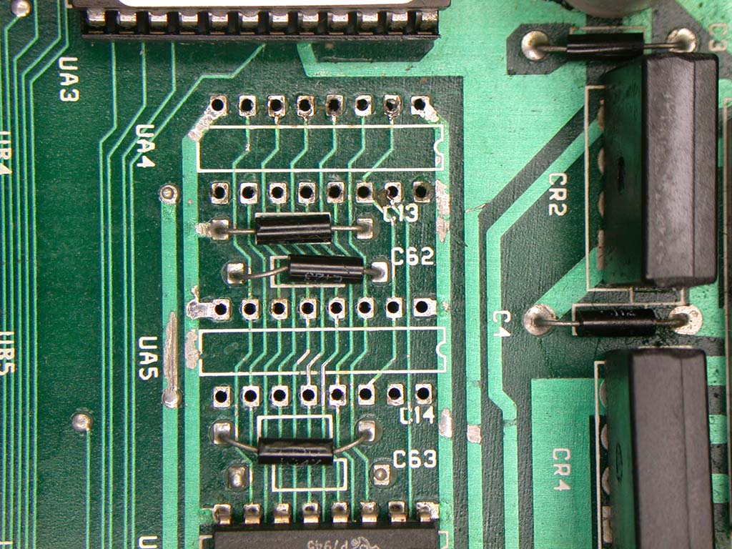
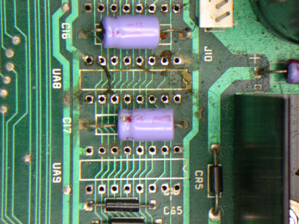
The first thing to do was clean it up so I removed all of the socketed chips and gave it a bath
in soapy water, rinsed in clean water then dried it off outside in the sun for 1 whole day. After that I replaced all of the old MOS mask
ROMs with EPROMs (2532 are directly 1:1 compatible) and changed all of the 37 year old single-wipe sockets for new dual wipe sockets
including all of the larger 40 pin sockets. Removing the sockets also meant I could clean the crud off the board under the socket too.
Changing the ROMs & sockets didn't help but one of the ROMs was unknown and undumped!! It was the editor ROM for a 50Hz, graphic keyboard,
80 column type PET which is not available on the net. I promptly sent that to the master PET ROM archive at zimmers.net for safe keeping :-)
Next step was to change all of the 4116 DRAMs. They are also 37 years old and I figured at least one of them was bad or soon will go bad so I
ordered 16 new (old stock) DRAMs and new dual-wipe sockets and just replaced everything. I wanted it to be stable and reliable for many
years to come so there's really not much point trying to diagnose if one or two RAMs are bad, better to just change it all and be done with
it. While doing that I realized that this machine was a 16k, 80 column board which had been upgraded to 32k by someone who was not very good with desoldering
parts and had damaged the board under the chips. That explains the amateurish patch wire the size of fence wire on the bottom side of the board under
the RAMs! With all of the RAM removed I traced all of the RAM tracks and found no other track damage. Even after changing all of the RAMs it
still wasn't working properly but with all of that changed at least now I knew the problem was not ROM or RAM related.
I powered it on the next day and it was totally dead! After testing some things I realised the syncs on the 6845 were missing. The input
clock was there but no syncs, and since they are outputs it had to be a bad 6845. I changed it and the computer sprung back to life with the same
fault as before. So the 6845 just died on me in the middle of the repair!
All of the caps were 37 years old too, so the next thing was to replace all of the caps. Still no improvement on the actual lock-up issue so
I figured I had a logic problem. Over the course of about another week I slowly checked each chip but it wasn't an easy task because most of
the time it was working and when it locked up everything would stop. Powering off/on would make it work again perfectly for some random
amount of time. In the end I consulted the schems and started just changing all the logic in the memory control section since that too was
all 37 years old. In reality it needed all of the logic replacing but that was a huge job. After replacing about 1/2 of the logic the whole
thing just died again and this time it was permanent. There were no clocks anywhere (not even on the CPU) but the main crystal was ok. Most
of the time it wouldn't boot at all but when it did (once in dozens of power-ups) it locked-up within 1 second and the monitor would make really
bad noises like it was out of sync and receiving the wrong frequency. That allowed me to narrow down the search to the clock generation
circuit. I eventually found the bad chip, a 74LS164 at location UE3. I tested it in my IC tester and it failed. After
replacing that chip it fired up immediately and continued to work for the rest of the day without any issues so I knew it was fixed 100% :-
)
I wanted to see if the PET experience could be better so I looked around on the net and found a replacement ROM that has been reverse
engineered from the original ROM with additional features. These include Escape key sequences, a soft reset (like CTRL-ALT-DEL on a pc), a
DOS Wedge and a 40/80 column soft switch mode. I burned a new EPROM, fitted it and it had some issues so I contacted the maintainer and he promptly fixed the
problems and sent me a new binary and it worked great! If you have a PET and are interested in adding more features like I mentioned above
check out the site here

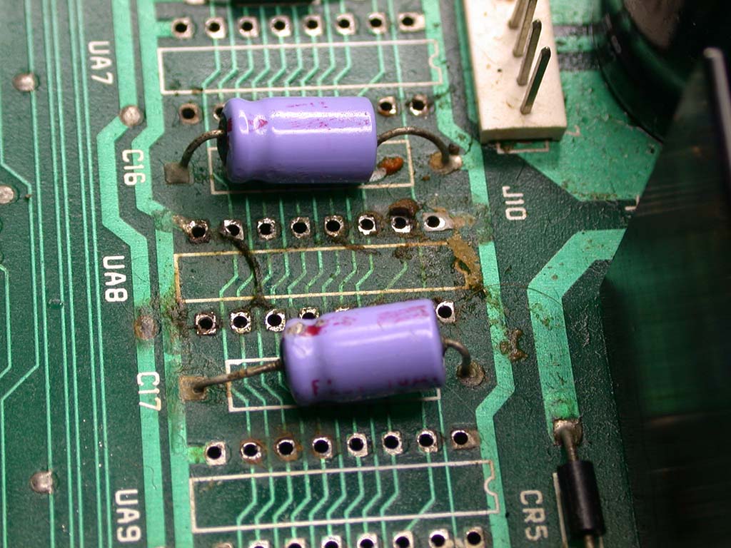

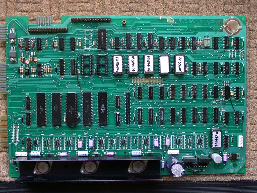
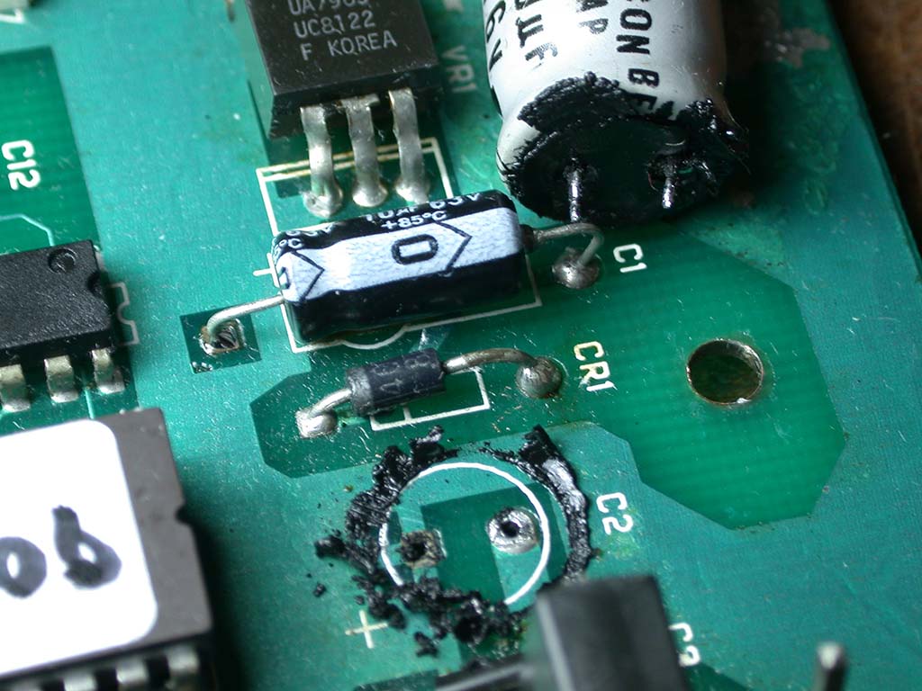
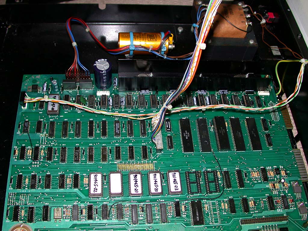
Commodore Amiga Power Supply 391029-05 Repair
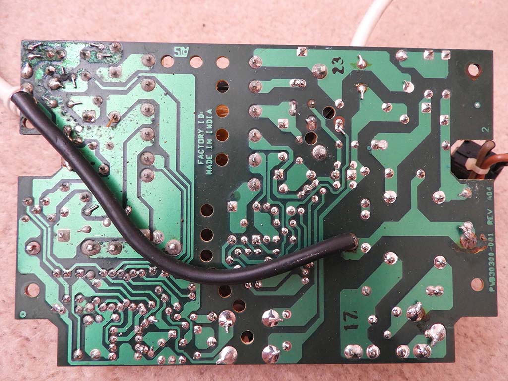
This is one of the myriad of Amiga power supplies made by Commodore, model 391029-05 and is one of the light switch-mode power supplies.
When powered on it appeared to be working but when powered off it would make a whining sound that would get lower in tone over about 5
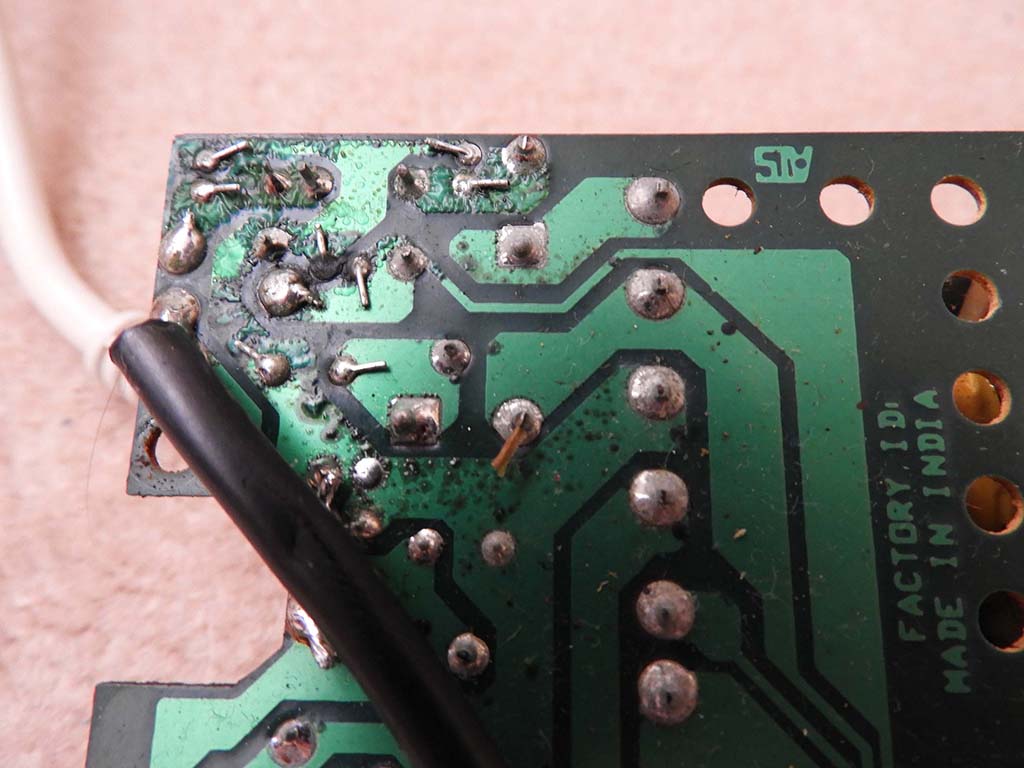
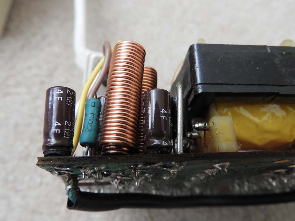
seconds before stopping completely. I suspected the caps so I opened it up and found several bad caps that had bulged and leaked. They had
also leaked through to the bottom side of the PCB causing some corrosion. I removed all of the caps, cleaned up the board and replaced all
of them with good new caps. The noise issue was still there but for only 1/4 of a second so I figured it was normal. I believe the noise is
the switching transistor trying to run but because the AC has been turned off, the large filter cap drains quickly and makes some noise via
the transformer winding. I don't know if that was by design or not, but it's actually a good thing because the big filter cap is totally
discharged. I measured it after running it for a while then powering off and the big filter cap had no charge in it. In any case the tiny
1/4 second noise is not a fault. I've heard a similar sound when turning off some electrical appliances. I tested the output voltages and
found there were none! After about 2 minutes the voltages measured ok! So there was a delay in the power supply starting up. But it couldn't
be caps because I just changed them all with exactly the same values that were in there. Or could it? I checked an identical Amiga power
supply and found that some of the caps were a different value! I changed them for the other type and it fired up immediately. I checked the
caps I removed and they measured OK so they were just the wrong value and likely changed by some amateur years ago. At that point I was
curious what the caps did so I went looking for a schematic of this power supply on the net and found nothing. So then I looked for *any*
Amiga power supply schematic and found nothing! That just isn't right so I decided to reverse this one and make a schematic of it to see how
it works. After a few days it was done. Below is the schematic for this power supply (391029-05) which I am making available for the benefit
of the Amiga community. The schematic might look a little bit strange but that is by design. The PCB has no component locations or markings
so it makes it difficult to reference components between the schematic and PCB. The schematic is drawn using the same track layout as the
PCB, but viewed from above. Think of the PCB as being transparent and you can see the tracks below. That way you can look at the components
on the PCB and immediately know where to find them on the schematic. It is also drawn on an A0 sheet because I really hate multi-page
schematics. If you have ever tried to fault-find an Amiga motherboard using the available Commodore schematics you will know how much of a
pain it is to look through 18 pages trying to find a signal only to find it then goes off somewhere else and then you have to find that
signal, then off somewhere else etc etc etc. Drawing it on one very large sheet solves that problem. In today's computing world, multi-page
schematics are really a thing of the past in my opinion. For those who are curious, the schematic was drawn using Altium Designer version
16.
It would be good to continue to make more Amiga power supply schematics but the other versions are not available to me here. If you are
reading this and want to help, you can. If you have any of the other versions of the Amiga power supplies (heavy or light versions, dead or
alive) or any other Amiga hardware that doesn't have any schematics available and you would like to see them reverse-engineered so a
schematic can be created and made publicly available, contact me. Even if you can't help directly, you could
help by informing other Amiga users on any of the Amiga forums and similar places so that my request gets out there. You can also help by
simply donating via Paypal or donating any other unwanted Amiga or Commodore hardware. Hopefully I will be able to get hold of more Amiga
power supplies (or other hardware without schematics) and make schematics for all of them. That will benefit everyone who owns a real Amiga
so they can continue to live on! :-)

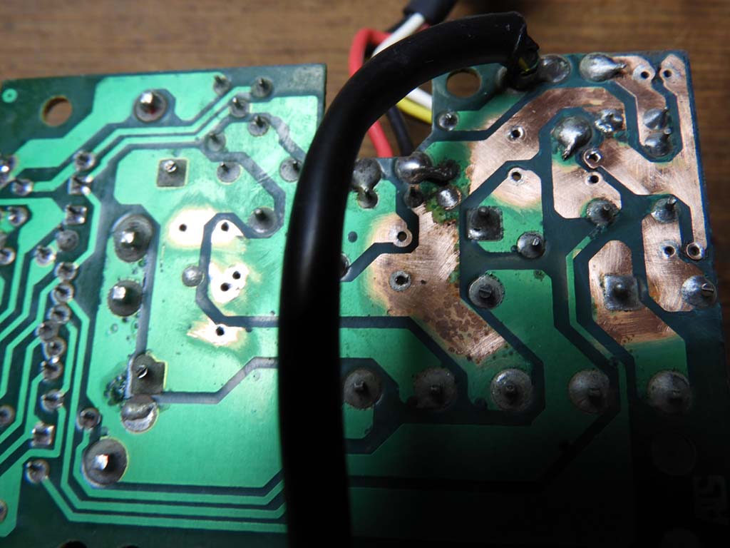
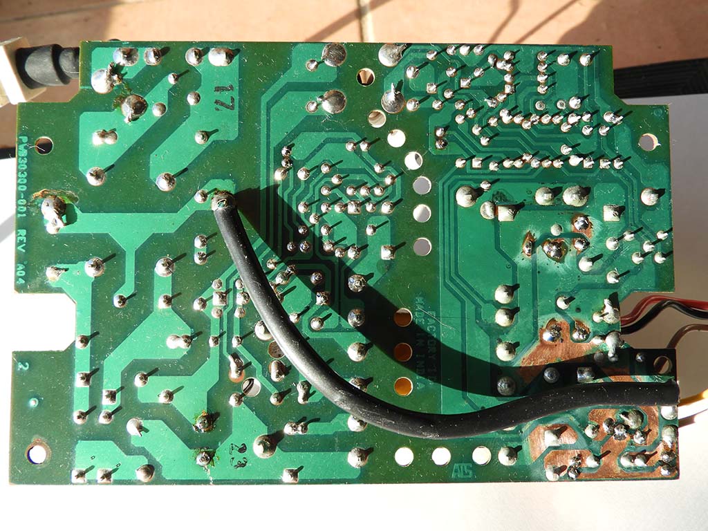
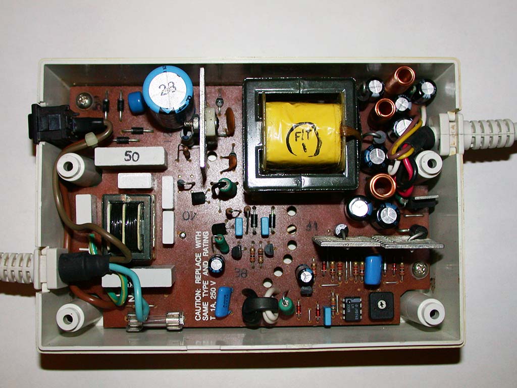

I'm also looking for a yoke from a 1084 or 1084S or 1084S-P or 1084S-P1 monitor (or possibly a 1081 may also fit). Basically any of the
models made by Philips should work ok.


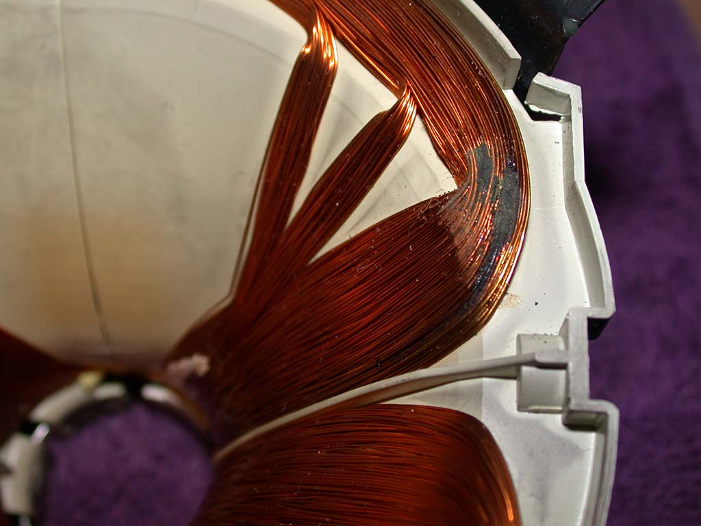
I was given a dead and rusted 1084S-P1 a while ago. The chassis repair took a long time to fix because of all the corrosion but now works
fine. The repair will be shown in a future news post. Unfortunately the yoke is shorted and corroded so it's currently still unusable. If you
have any faulty/not-working Commodore monitors and you want to part out some pieces please contact me.
21st February 2017
Some more decapping news! My Sega Model 1 DSP's were decapped and the ROMs have been successfully extracted. More news on the CAPS0ff blog. Please support CAPS0ff with funds if you can so more chips can be decapped.
Those chips have also been marked green on my Decapping Status Page
16th February 2017
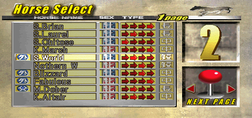
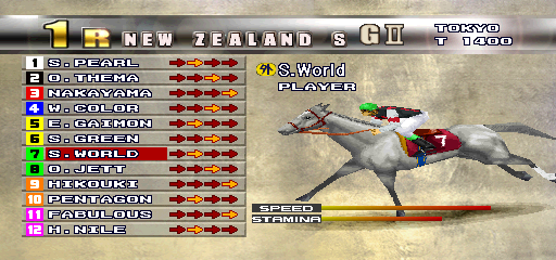
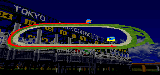
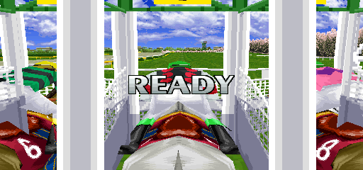
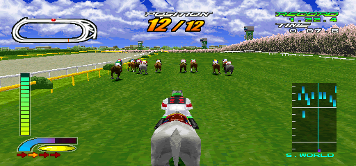
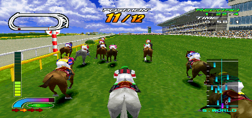
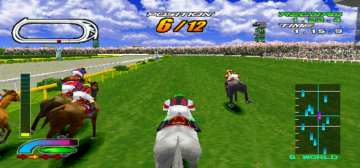
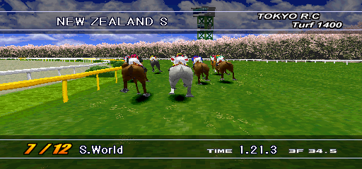
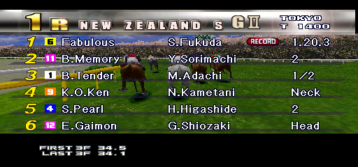
I redumped Gallop Racer 2 and now it's working in MAME. Here's a few screenshots....






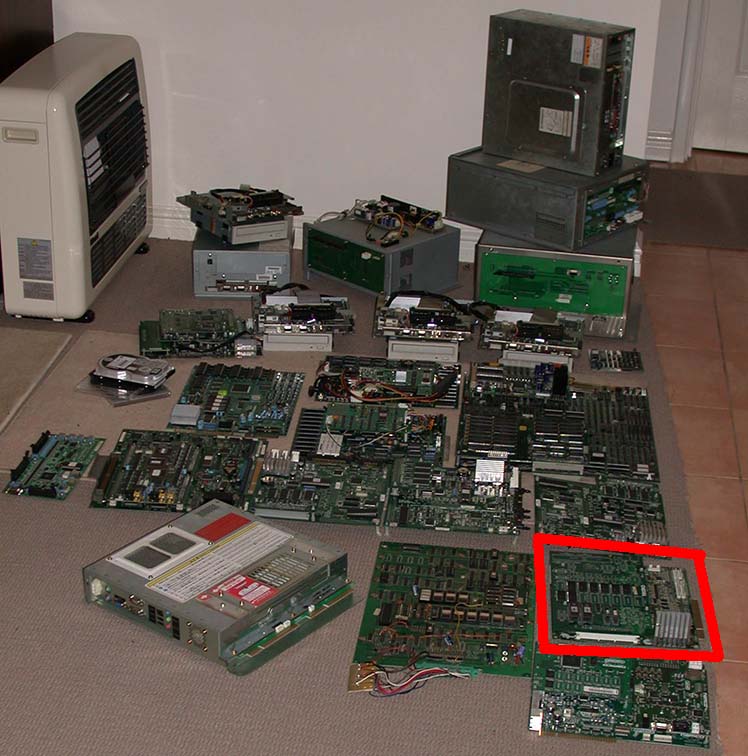
This next pic shows the PCB in the Mother-Load that is shown on 15th July 2016.....
26th January 2017
At my request, CAPSoff has decided to consider decapping chips that are still sitting here in my Guru Lair or other chips that may be
acquired in the future.
Because of the costs involved with decapping and processing chips, to do all of the current chips and any future ones that come along, they would
like to get some support from the emulation community in order to keep the project moving forward. You can
read about it on their blog here.
They also recently did some decapping work on some PIC16C57 chips and you can see their blog entry about that here.
7th January 2017
A few years ago around the middle of 2009 I received some items for decapping. Technically they were not really needed but they were sent anyway.
However this was an extreme case of severe butcherism because the chips were received like this.....
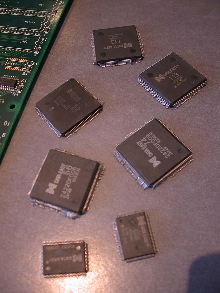
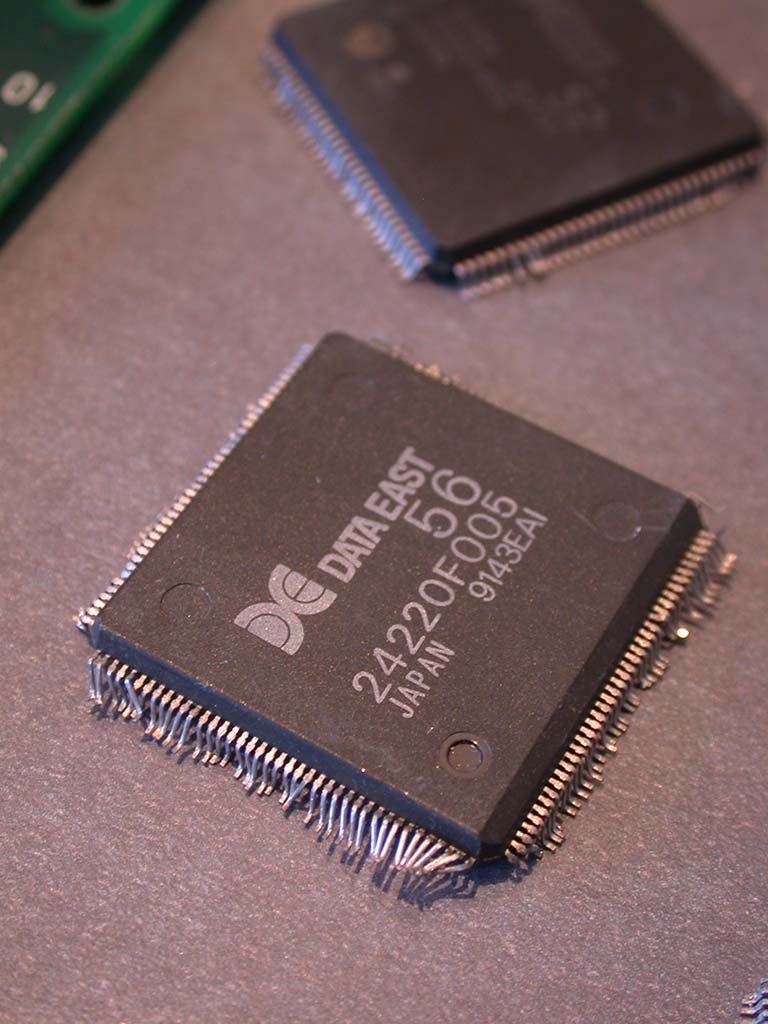
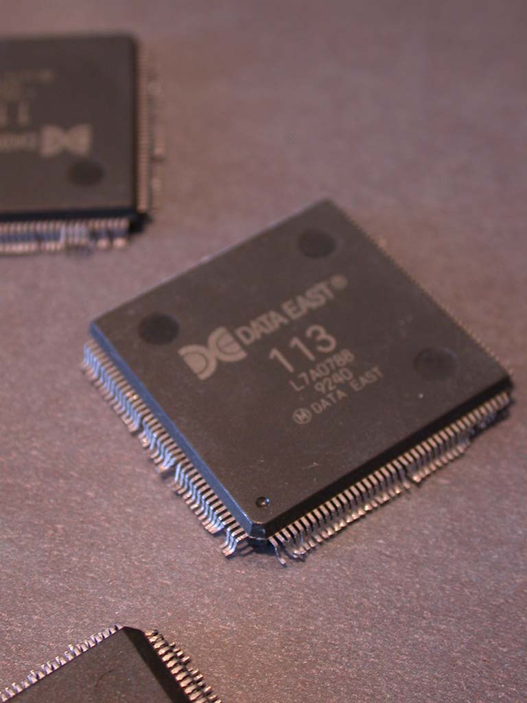
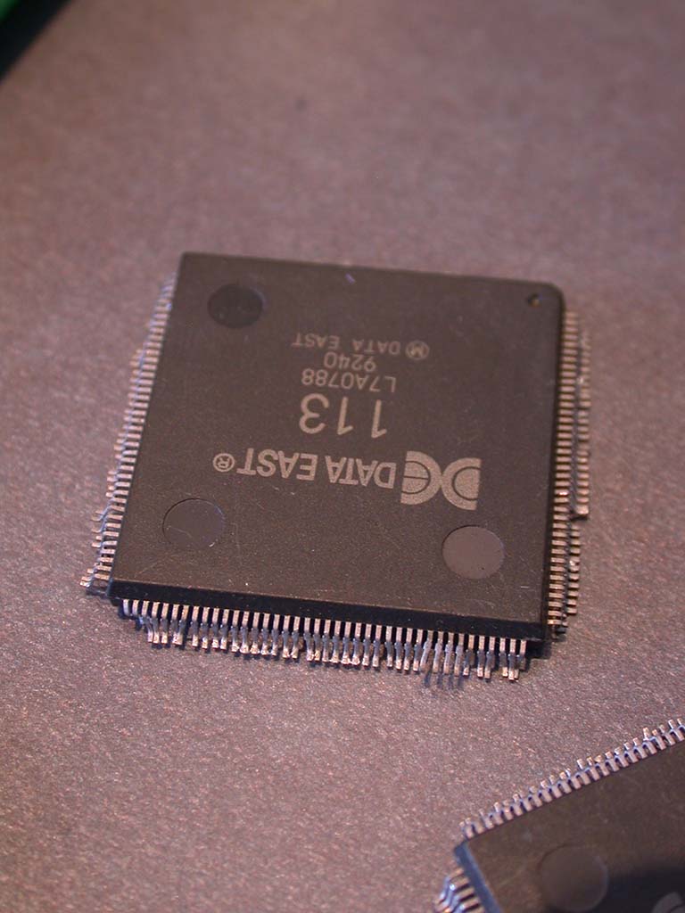
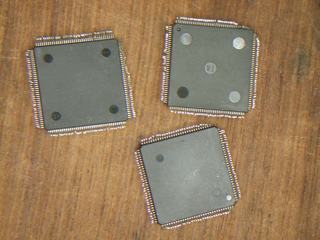
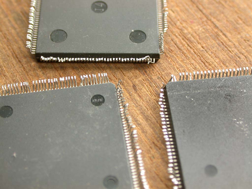
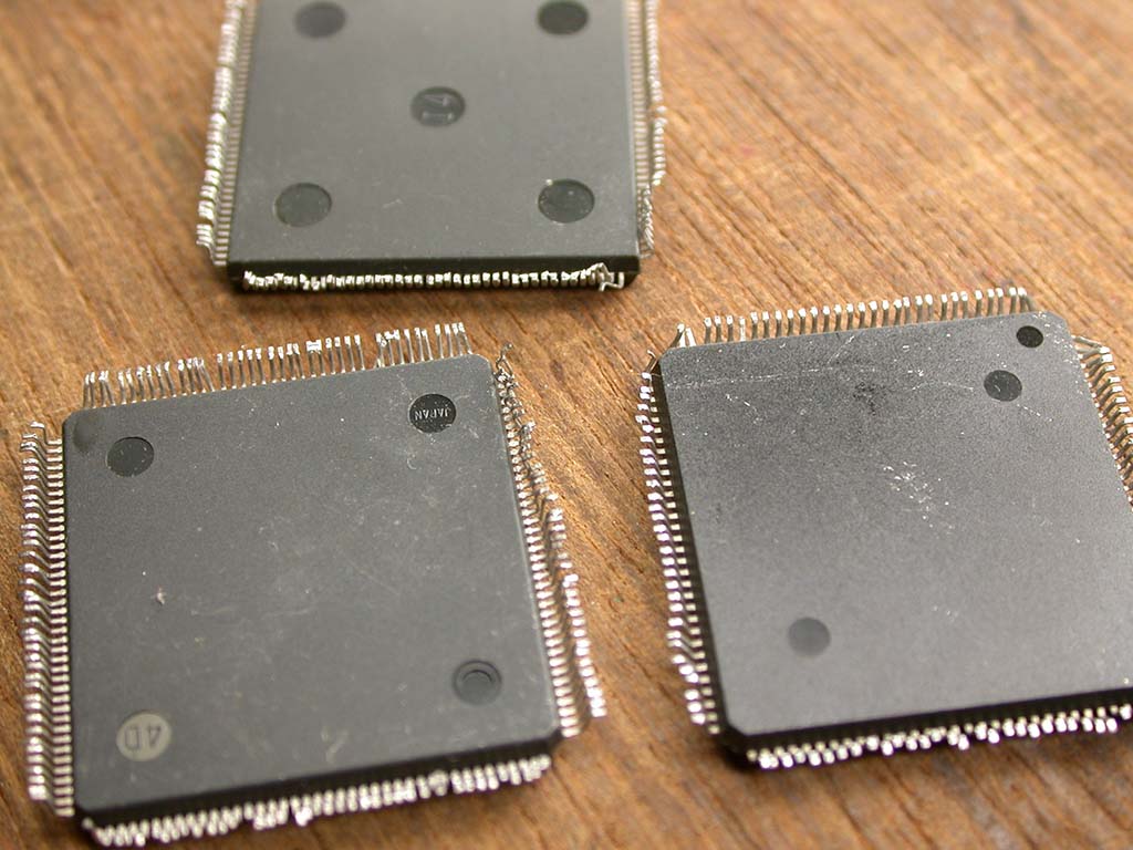
The PCB was also sent, minus most of it's chips!

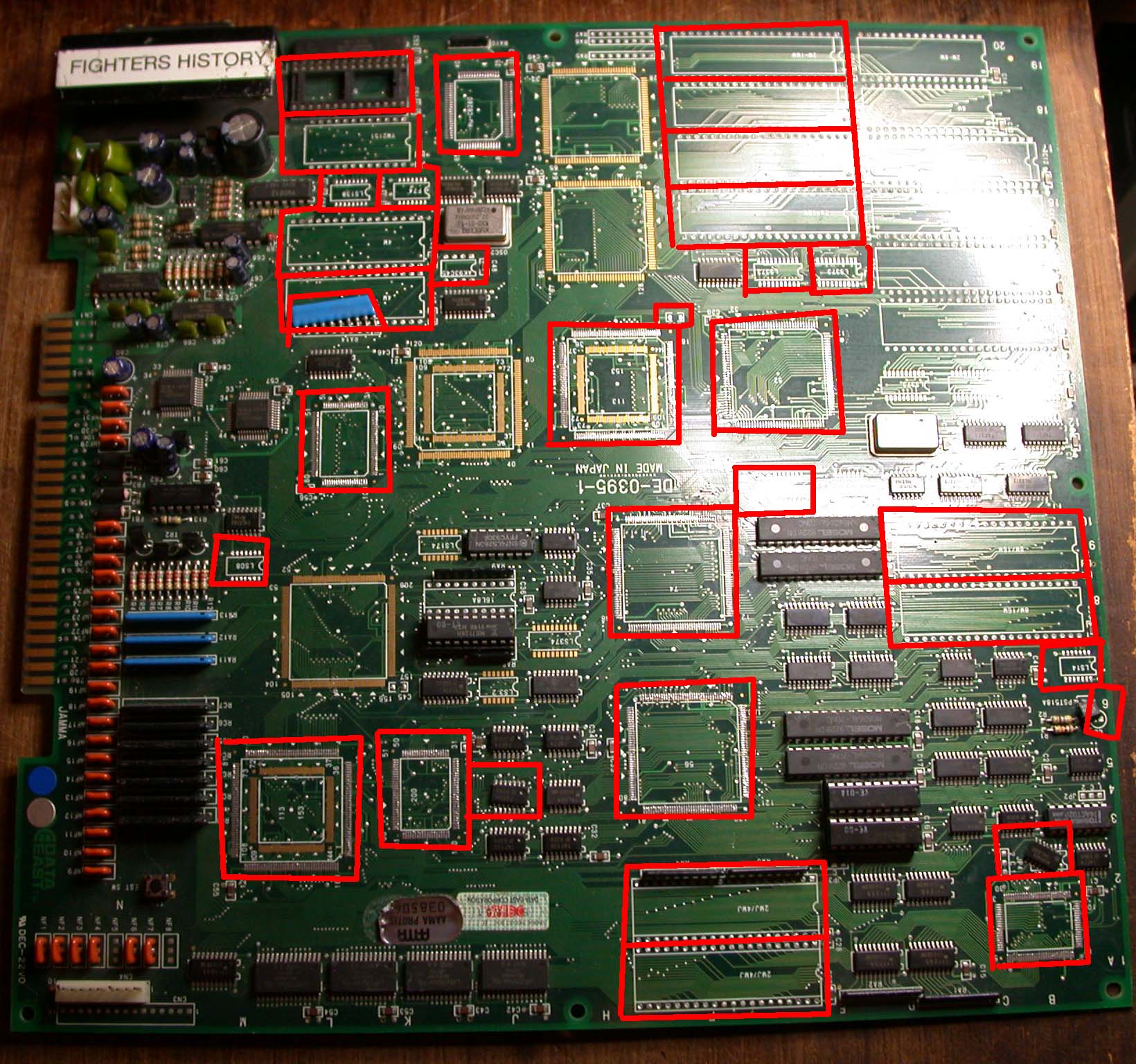
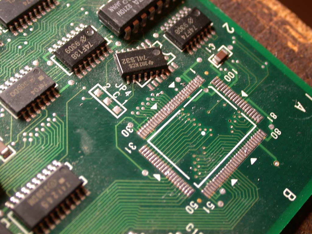
Clearly this was scrap, or so I initially thought, so I basically tossed it on my pile of junk and it sat there for several years.
We all now know that the chips were not really needed for decapping because the emulation is working fine thanks to fantastic reverse-engineering
work by Bryan McPhail. It always disturbed me that this PCB was treated so badly and was scrapped for no good reason. Recently I came across it
while looking for some other stuff and I decided to make an attempt to resurrect it to it's former glory.
The first thing was to determine if all the chips I needed were available. After a bit of searching I found all of the custom chips except
the HuC6280, but I had a couple of spare chips lying around so I had that missing chip in stock. There were several other chips missing including
several SMD logic chips, a YM2151 sound chip, a few SMD capacitors, an electrolytic capacitor that feeds the reset circuit and a DIP8 EEPROM.
And of course all of the ROMs were also missing. I had all of those parts either in my parts bin or on some scrap PCBs and the ROMs can
easily be replaced with EPROMs so the re-assembly work could begin!
The next step was to clean all the old solder off the PCB pads where the missing chips were. It was a pure miracle that the fragile solder
pads were not broken or ripped off the board by the idiot who did all this damage. It's an easy job to remove solder so after an hour that
part was done.
Now came the really tedious and boring part.... I had to bend all of the legs on every custom chip back to where they
were supposed to be *very carefully*, hoping the legs were (a) all present and (b) didn't break off as I manipulated them. After many hours
(about 1 hour per chip) the job was done and everything looked as good as it could get... not perfect but very close.
Now to start mounting the chips. I started with the logic chips, capacitors and other smaller parts then moved onto the custom chips. One by
one they were soldered into place. Because the chips were not perfectly straight and flat within 0.1mm (the normal tolerance) I had to mount
each leg one by one (close to 800 legs!). I couldn't do the usual drag soldering method and mount the chip quickly. Every leg had to be held
in place carefully in line with the PCB pad and then heated with the soldering iron to make it stay there. Because I worked in
engineering for 30 years I have developed special tools to help with that kind of task so it went fairly smoothly. After many many hours
(maybe 24 hours across about 3-4 days) everything was in place and it was time to power on and see if it was alive.
The first screen I saw was full of garbage tiles so I thought it was not working, but looking closely at the screen I could see some white
text among the pink, blue, white and purple mess that read.....
"WARNING GAME MODE SETTING ERROR"
By luck probing around, I accidentally shorted two pins on a logic chip near the CPU and to my amazement it booted into the game! The
backgrounds were scrambled but it was running! The title screen graphic "Fighter's History" was there but the "Copyright Data East 1993"
text was also scrambled, mostly just random dots. Most of the initial Data East logo first boot screen was also OK but some sections were
out of position. All of the sprites were OK. The game was playable (i.e. controls were working so I assumed the custom I/O chip was OK) and
sound was working too. Things were starting to look very promising!


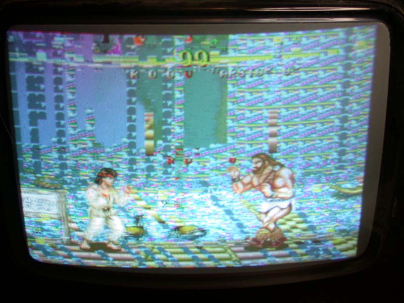
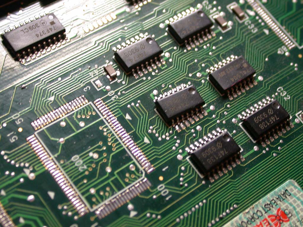
I figured some legs on the custom chips were loose so I went around every chip and checked them and found a couple of loose legs. The
graphics were improved slightly but it was still not fixed so I started looking closer at the bottom of the PCB. Because this board had been
attacked with a heatgun there were many solder blobs on the board where the solder in the vias had come out of the hole (because it was
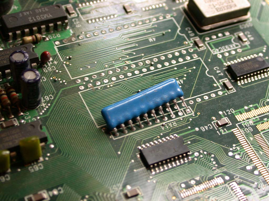
boiled) and was sitting on the PCB surface as a little solder ball. You can see some of the little balls in the 11th pic shown above (the
PCB pic with the blue resitor array pack). There were dozens and dozens of those little balls all over the PCB top and bottom. This
particular PCB has vias that are *really* close together and some of the solder balls were causing shorts. I cleared most of them before I started
soldering the custom chips on but missed a few. After clearing some more blobs it improved a bit more. The corruption seemed to change
slightly with each re-boot. I checked a few logic chips connected to the 56 and 74 chips (used for generating the backgrounds) and found a
74F373 SMD logic chip that was a bit random. I pulled the chip and tested it and found it passed the test only about 50% of the time so it
was faulty. This was probably the original fault as I'm guessing this board came off ebay. After changing it the graphics were no better but
at least now the corruption was consistent.
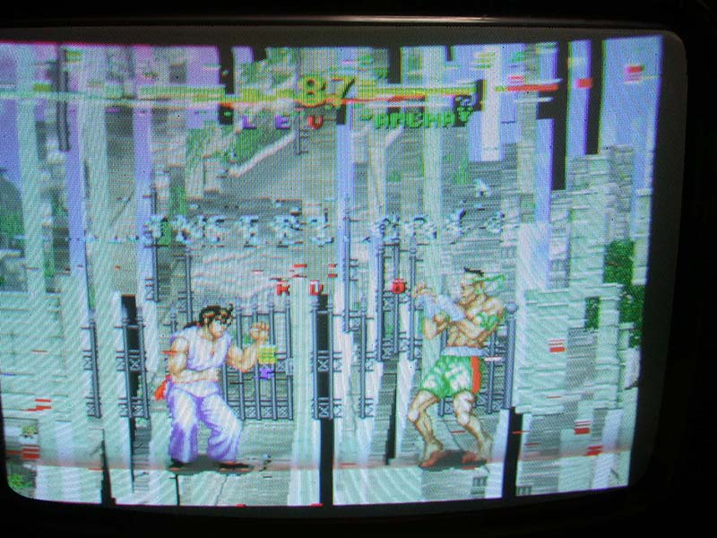
The pic above shows the backgrounds are now partly correct.
At this point I needed to get some confirmation about a few things so I contacted Bryan to get his opinion. MAME is really great for playing
games but there's very little real world repair info in MAME (aside from my Guru-Readme's hehe!) to help with problems like this. At least
not for the average person who doesn't understand the deep down guts of the code and how it works. He told me the bootup warning error means there is a
problem with the 93C45 EEPROM and the graphics fault was likely shorted or loose pins on the background graphics chips. In this case that's
chip 56 and/or 74.
On a regular board a bad line will usually give a solid bad line/jailbar on the graphics. But on Fighter's History the graphics chip uses
a form of encryption that mixes up all the bits within a 4K block or something so they aren't stored linearly. This means that a bad line
can cause the addressing to go completely wrong over the whole block so everything appears completely scrambled. So it could just be 1 bad
line causing the problems.
I had a look at the EEPROM problem first. After checking I realized what was wrong. Urgghh! I had used a 93C46 EEPROM and it should be a 93C45
EEPROM. They are sometimes compatible depending on how they are configured. In this case the 93C45 EEPROM is fixed at 64 bits x 16-bit and a 93C46
can be configured to either 128 bits x 8-bit or 64 bits x 16-bit when a specific pin is held high or low. That pin was not set because the 93C45
doesn't have that option so it was the wrong chip. After finding a 93C45 EEPROM in my parts bin and changing it the fault went away and the game booted
up fine. Of course that didn't fix my graphic problems.
I went around the graphics chips again even more carefully than last time and found a micro-hair of solder shorting 2 pins together. I
cleared that which improved the colors slightly. Then realizing there was nothing else to look at (all chips were mounted 100%), I double checked
the bottom side just in case there was another solder blob causing a short. Sure enough I found one. After clearing that it booted up and was 100% fixed!
Success at last!!
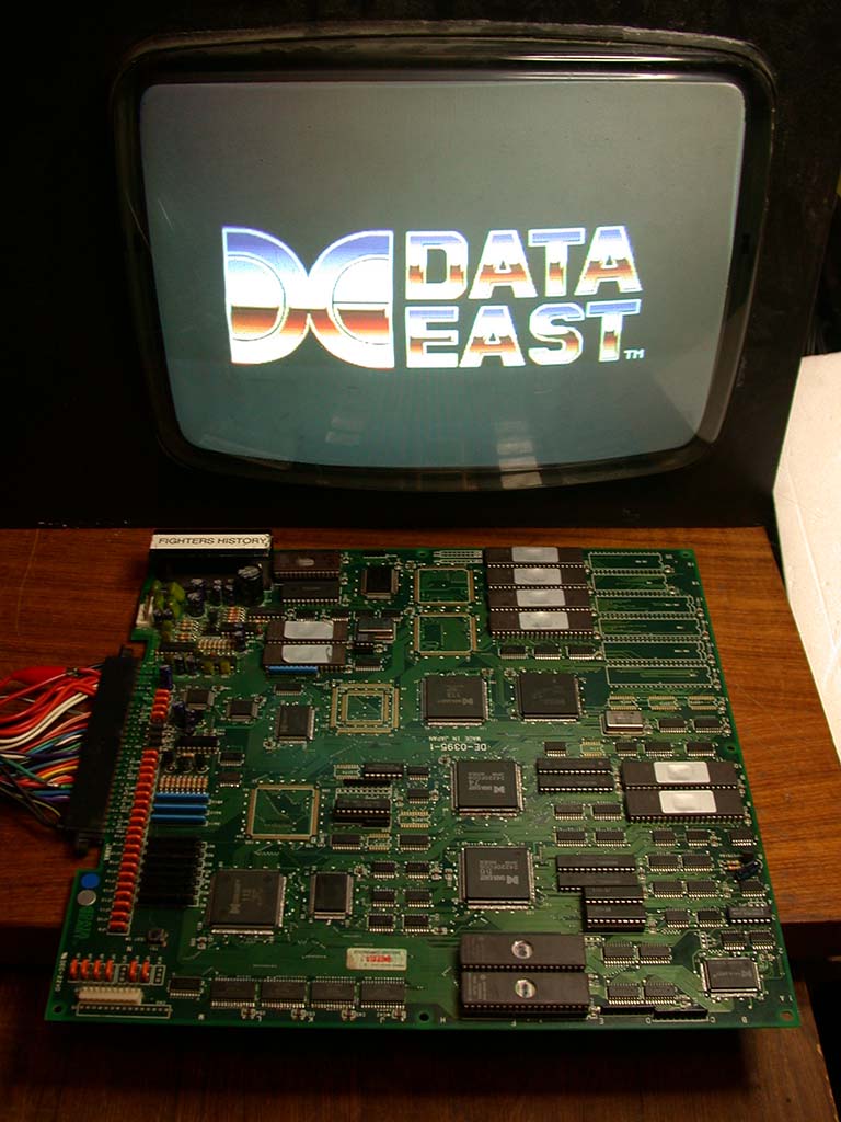
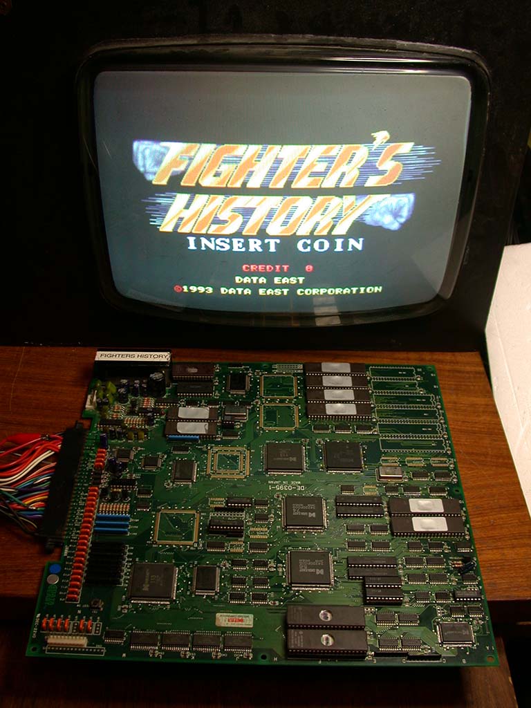
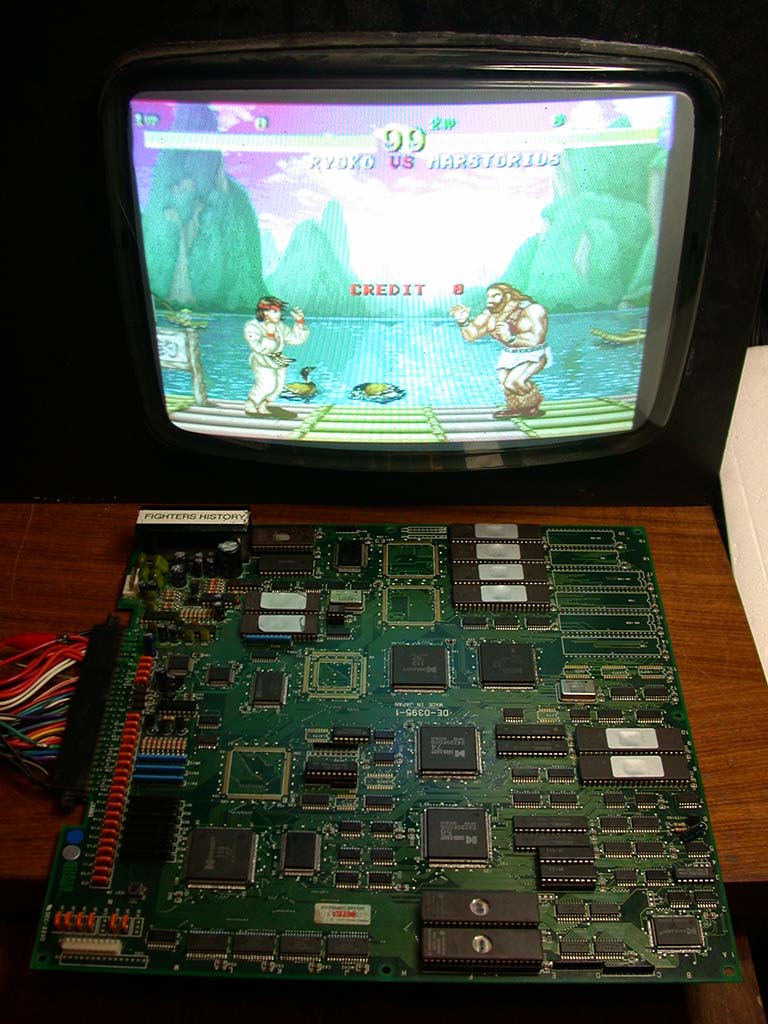

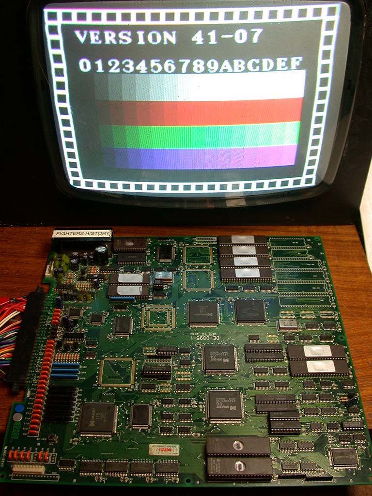
All cleaned up and ready to go. WOW! What an amazing transformation! :-)
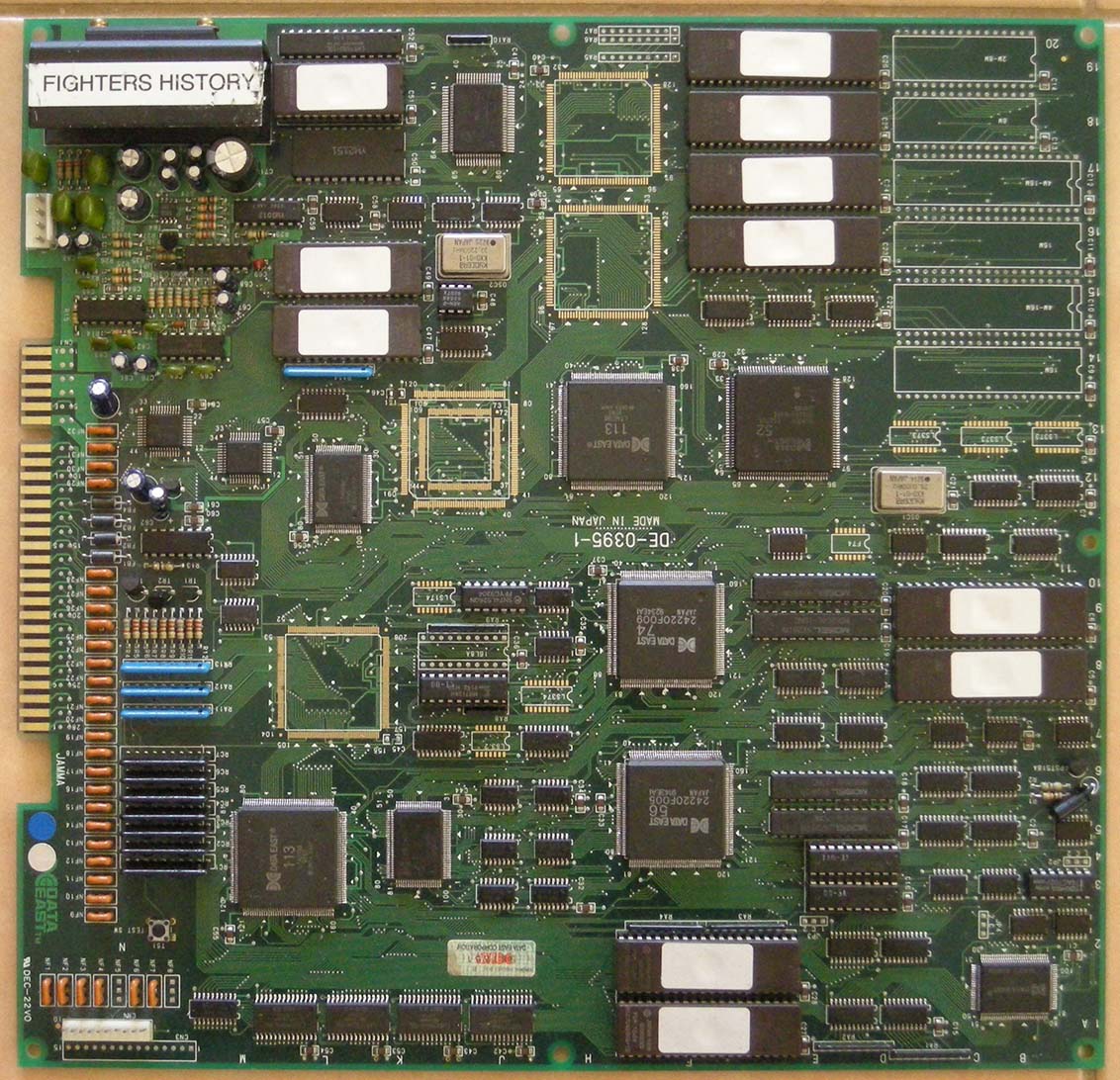
So after reading all of this you're probably wondering who the butcher is, right? Well, normally I would not mention that because this was
sent for a useful purpose. But of course if you have been reading these pages for some time you will know I take great pleasure in giving
assholes who have screwed me over in the past their just desserts. This is no exception. The funny part is he can't even deny it. It's
documented ALL over the internet and a simple
google search will reveal the truth of who this horrendous butcher is. Hahahahah!!!
All I can say is if you value your undumped board DO NOT send it to him for dumping!
At least this ended well because it was sent to someone who could properly take care of it (i.e. me!) and now I can sell this board on my
Items For Sale page :-)
So now with all the excitement over I can use the working PCB to discover something useful for MAME..... I noticed recently a small change
to MAME relating to the volume chip used on these Data East boards. Unfortunately no one has documented exactly what chip is used for the
electronic volume control so the change is just guess work. The real PCB does not have a volume pot on it and volume is
adjusted in the test mode electronically. So I had a look, did a bit of research and identified the chip pretty quickly.
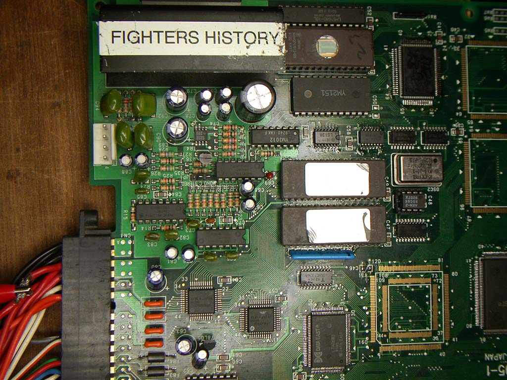
The Fighter's History PCB (and others like Night Slashers etc) use a Mitsubishi M5222FP Voltage Controlled Amplifier (VCA) in a tiny SOIC8
package which is used for the electronic volume control. You can see that in the above pic just near the group of larger electrolytic
capacitors. For those curious about the chip the datasheet is here.
|
|


