10th December 2022
If you missed the previous repair logs you should start at the beginning (28th November log below) otherwise none of this makes sense ;-)
p.s. Some minor edits/updates were done here so the date above was changed from 9th to 10th. There's an extra pic at the very bottom too...
Continuing on with the Defender repair, the board now refuses to go in-game and just shows the rug pattern continually with all 4 LEDs stuck
on. The LEDs are controlled by the PIA at 4E on the top board so that seems like a logical place to start looking for the problem. Before I
do that I thought I would try an easy fix for the sound. I swapped the 6808 CPU with a spare I had lying around then pressed the sound test
button but no go. So I swapped the PIA connected to the 6808, pushed the sound test button and now the sound is back heh! I put the original
6808 CPU back in and there was no sound so both the 6808 and the 6821 connected to it died! I also confirmed functionality without the
bottom board connected. Basically I just wanted to know if the test sound works without the CPU board connected. It does, only power is
required. A working sound board will output the test sound without anything else. Good to know. Getting back to the no-boot problem, I
swapped the PIA at 4E (which I swapped previously) but there was no change. I probed the PIA chip with my logic probe and most of the pins
are active. Some pins are inactive but at this stage I don't know what they do. I need to have a look at the 6821 datasheet for some more
info...
The chip has a reset signal on pin 34 and clock input on pin 25. The reset goes low/high when powered on so that is working. After the reset
all the port pins (for example those connected to the Q connector and the LEDs) go high. In order for the PIA to turn off the LEDs those
port pins need to go low and the chip has to be told to do that by the CPU. The high signal on pin 3 which is connected to the Q connector
Advance button is probably floating and triggering continually when the audit screen shows up on first power-up. It appears the
6821 is not running properly. I've already swapped the chip for a known good chip so it can't be the actual chip at fault so there's
something deeper involved. I probed the clock pin with my logic probe and it shows only a low signal. However I measured the clock with my
frequency counter and it is correct at 1MHz. On further inspection that clock is the very same clock that comes from the CPU, as shown
here...
The E clock goes to the top board through flat cable connectors A pin 34 and B pin 14. I verified that it is actually connected. Hmmm, so
maybe the problem is this clock on the bottom board? I went back to the bottom board and checked the E clock on the 6809 (pin 34). It
measured 1MHz. I remember looking at this when I did some of the CPU board repairs earlier and I wasn't happy that the E clock was not
showing up on my logic probe, which should make a beeping sound when probing a clock. It was only showing a static low signal. At that time
the board was booting so I dismissed it and moved on. I need to check it with the oscilloscope. Here's the Q clock and E clock shown on the
scope...
According to the Williams Defender Theory of Operation manual these clocks should be the same but are offset by 90 degrees. The height of
the E clock is less than the Q clock by about 1/3rd. Maybe something is pulling it down? I removed every chip that connects to the E clock
and unplugged the top board A/B connector cables. The E clock did not change!?! Hmmm, but this clock is generated by the CPU, could it be
bad? I swapped in a different 6809P CPU but it didn't make any difference. I also noticed that the CPU was getting very hot which is not
normal. With all the logic chips connected to the E clock removed the only other parts connected are some diodes (check the schematic above
with the red line on it). I removed all 4 diodes and checked them. Three of them checked ok, one came up different....
Looks like this one has changed sides and now wants to be a 112 ohm resistor hehe!! I decided to replace all 4 diodes with new and more
common equivalent 4148 general purpose small signal fast switching diodes. I re-checked the E clock on the scope and now it's the same as the
Q clock :-)
I put back all the chips that were previously removed and re-connected the flat cables, powered on and there was no change! I probed the E
clock on the CPU with my logic probe and now the logic probe beeps correctly. I re-checked the E clock on the 6821 at 4E and it was now good
so at least that issue is fixed but the 6821 still isn't working. Checking the datasheet shows there are 3 chip-select pins 22, 23, 24.
These should all be active when the chip is working. The datasheet says CS0 and CS1 must be high and CS2 must be low to enable the chip. I
probed them with my logic probe. CS1 and CS2 were active but CS0 was only a low signal. The schematic page (above at the top of this log)
shows that CS0 (pin 22) is connected to pin 6 of a 74LS25 Dual 4-input NOR Gate with Strobe at location 6C. Checking that pin with my logic
probe showed the same static low signal. The inputs on the 7425 were active (except pin 2 which is tied to ground) so it appears this chip
is bad. I piggybacked a good chip on top but it didn't help. One trick that can sometimes work is bending the affected output pin out
so it doesn't touch the bottom chip and connecting it directly to the other connected pin but also lifting that pin out of the socket.
Fortunately the 6821 is in a socket so this isn't difficult to do....
It worked! The game booted up and showed the "INITIAL TESTS INDICATE UNIT OK" message, but then rebooted back to the rug pattern. This was
progress at least. I pulled the 7425 and tested in my chip tester...
Yup it's bad! Pin 6 is stuck low. I swapped out the chip for a new one and powered on again. Unfortunately the board won't boot
into the game, it just shows the following then resets....
If I leave the game off for a minute then power on I get the audit/book-keeping screen and the number auto-increments then it resets then it
shows the UNIT OK message and resets. I don't like that the CPU is very hot, maybe it cooked itself. The problem now is I don't have another
6809P. Well I had one but I had already swapped that out a few days ago. I tested that one too and it's worse, only shows the rug pattern
then resets, no UNIT OK message, so probably that one cooked itself too. I do have a bunch of much newer 6809EP chips. Fortunately the board
can be easily re-strapped to take a 6809EP. Let's check the schematic again.... (same image from above re-used)
This has a little table showing that jumpers JA, JB and JC can be changed. Currently it's set to OPEN, OPEN, CLOSE for the 6809P. For the
6809EP it needs to be set to CLOSE, CLOSE, OPEN. The PCB has no markings for these jumpers so I traced them using my multimeter. Jumper JC is
located next to the PROM DF11....
and jumpers JA and JB are located at the bottom between two pretty rough-looking 7474 logic chips at 7J and 7L...
Note the blue wires are factory wires connecting 7J pin 3 to 7L pin 9 and 7L pin 2 to the top jumper 2nd pin. These wires must remain in
place regardless. Also note the small cut on the trace near 7L pin 4 is also a factory cut and must remain open. The top jumper is JB and
the bottom jumper is JA. JB connects to the CPU pin 35 (Q clock) and JA connects to the CPU pin 34 (E clock). A 6809EP requires the E and Q
clocks to be provided externally whereas the 6809P generates those clocks internally. To re-strap for a 6809EP simply open jumper JC by
removing the wire and link jumpers JA and JB with a wire, like so....
With these changes I plugged in a 6809EP CPU, powered on and it boots into the game. We're up and running!!!
So this proves the old 6809P CPU fried itself :-(
This makes sense now. I remember many years ago when doing a repair on a Namco System 2 Suzuka 8 Hours 2 PCB and it had a similar issue
where the 6809 CPU for sound was burning hot and sound didn't work. That turned out to be a missing Q clock caused by a broken trace. I
wired that up and then the game had sound and the CPU ran cool again. So always remember if a 6809 runs very hot it might have an issue with
the Q or E clocks :-)
Now you might have just read all this (above) and thought ok that was an hour or two, right? Not so my furless friend. The above diagnostics
and repair work was figured out over about a 2 day period. This is 'normal' when owning a Defender. If you own one be prepared to spend
weeks repairing it multiple times ;-)
Note the garbage on the side of the screen is normal for Defender. The screen is supposed to be expanded with the monitor controls until
that is off-screen. The reason that is there is because the programmers are using part of the video RAM that is normally off screen for the
program due to lack of main program RAM on the main board. It's not an issue, just adjust it off screen so it doesn't show. The easiest way
to do that is to use the monitor test then adjust the screen until the rectangle is just showing on the edges of the screen and as a result the garbage will not show.
At this stage you've seen a lot of screen shots and they all look ok..... but if you recall in an earlier repair log I removed the blue
output transistor and used it for the blanking circuit.... haha you've forgotten about that haven't you ;-)
So how did I get the correct colors? It was actually pretty easy. I simply replaced that transistor with a compatible one. In this case a
2SA509 can be replaced with a 2N3906. But not always. It depends on how it is being used. A 2SA509 can provide more current up to 1A whereas
the 2N3906 can only provide 200mA. The color circuit definitely doesn't need 1A and the 2N3906 has compatible parameters for everything else
so it's fine as-is. These same transistors are used on a Gauntlet PCB for the color drivers (I bought these to repair a Gauntlet PCB many
years ago) so they are ok for most general purpose PNP color drive transistor uses. I can always change it later if necessary for the exact
same transistor as the original. The interesting thing about this transistor is that the legs don't need to be swapped. It fits perfect
without any modifications. This color pattern from the test mode shows everything is working fine :-)
The missing battery is starting to piss me off so let's fix that. I quickly assembled one of my 5101 NVRAM adapters that I designed for a
friend a few years ago....
We don't need no steeekin' battery LOL! Now the game boots up and remembers the settings when powered off :-D
Now it's time to do some testing. The game is pretty hard so I went into the settings and changed the free ship level to 5000 points and set
the number of starting ships to 20 hehe! I played the game for about 20 minutes and everything was going well.... then as expected something
else happened... the sound stopped again hehehe :-/
There's not much in the sound circuit. A ROM, RAM, CPU, 3.579545MHz crystal and a few logic chips. I removed and read the ROM and it is ok.
I removed and tested the 6810 RAM and that also passed. I didn't have any more spare working 6821 PIA chips. I pulled the 6821 and put that
into the PIA socket used for the controls and then went into the test mode and checked all the controls and they all work so the PIA is ok.
The clock input on the CPU measures correct with my frequency counter... however the crystal only shows as a static low when probing with my
logic probe. The CPU has an E clock output which measures 894.8kHz (i.e. correct) and probing that with my logic probe also makes the probe
beep which is correct. I changed the crystal and 33pF load capacitors but it didn't make any difference when probing the clock with my logic
probe. Measuring some crystals directly can be tricky as they can be sensitive to capacitance just touching it with a probe or even a
finger. To get around that you can feed the clock into a buffer chip and measure the output on the chip. This is a 7414 which inverts the
signal so I fed the inverted output pin 2 into pin 3 and measured pin 4 which is inverted again back to normal...
This is of course only for testing purposes. I removed it after verifying the crystal was ok. The probe beeps when checking that so it must
be ok.
I probed the ROM data pins and it is pulsing very strangely/randomly. Since I know the sound test works without the bottom board plugged in
I unplugged the bottom board and power-cycled the board. The data pins on the ROM were still screwed up but not as bad. I pressed the sound
test button and re-checked the ROM with the sound test running and the data pins had the same unusual activity. I manually reset the CPU by
momentarily grounding the CPU pin 40 (the reset pin) and the ROM went back to pulsing correctly, but only occasionally. I reset the CPU
several times and it would only work correctly now and then, not always. I pressed the sound test button and the ROM started pulsing
incorrectly again. There are a few logic chips in the sound circuit. The 7442 creates one of the chip select signals for the ROM and the CS
pin on the ROM also had the same strange pulsing so I pulled them but they all passed. However the 7442 input pins also had the same strange
pulsing on them. Those signals come directly from the 6808 CPU address bus. Could it be bad? I didn't have another spare working 6808.
Fortunately there's a way out of this problem. The 6808 is the same as a 6802 but without the 128 byte internal RAM. I bought a bunch of
6802 CPUs a few years ago as spares for my Bally Eight Ball Champ pinball machine which uses a 6802 on the sound board. I should be able to
use a 6802 and then remove the 6810 and it should work. Let's check the schematic and the 6802 datasheet...
The datasheet pin descriptions (page 2) shows pin 36 (RE) is for enabling/disabling the internal RAM. The schematic shows the 6808 pin 36 is
tied to ground with jumper 'J'. On the PCB this is done with a trace that is hard-wired to ground.
To use a 6802 this trace needs to be cut and tied to +5V. Strangely there's no factory alternative jumper location for a 6802 on the PCB.
But this is very easy to do using a solid wire taken from the end of a resistor and then link it to the nearest 5V location shown below.
Simply link the 2 points and the RE pin is set to enable the internal RAM on the 6802.
I removed the 6810 RAM, powered on and the sound is working! :-D
Another minor thing I forgot to mention, for proper testing purposes I needed to wire up a sound pot instead of just shorting the pot in-out
pins. Currently the sound is very low volume and hopefully wiring up a pot correctly will fix that. All I did was find an old 100 ohm pot
and just wire it up to my shunt plug and this allows me to adjust the volume.
This didn't improve the volume. Back to the schematic....
The schematic shows the 1408 DAC needs -12V!!! Urgggghh, where am I going to get -12V from???? Ah, that little DD1718PA buck boost board that
I used in the previous Sega SC-3000 repair will do the job nicely. I wired it up to nearby 5V and ground locations and wired the -12V output
to a point conveniently located right next to pin 3 of the 1408 DAC.
Of course remember that this is purely for my own testing and it will be removed before returning the board to the owner as the cabinet
already provides all the correct voltages without needing anything extra. I powered on the board and it's VERY loud. I adjusted the volume
down a bit using the 100 ohm pot and now it sounds great! :-)
It's time for a bit more testing so I played the game again for a few minutes. Then the board started glitching out again then reset! Now it
repeats the rug pattern test but briefly shows a bad RAM error. I went into the test mode and ran the RAM diagnostics...
The 4116 RAM is all running very hot and at least one has failed. Ideally all the triple voltage 4116 DRAMs need to be removed and replaced
with 4164 DRAMs which run cool and only require 5V. This is a common modification that is often done on Defender boards to make them more
reliable. On this board it is relatively easy to do with one small change to the PCB wiring. First let's check the original wiring on the
board which has been hard-wired, likely because this board was in a Taito Defender cocktail cab and the original harness wiring doesn't
reach. The power connector was removed from the PCB and hard-wired to a 12" length of wire and the power connector was wired to the wires at
the other end. It's not ideal but that's how it is so I'm not going to change it.
This wiring is a bit crap because Taito only wired up one 5V wire! I will add another thick 5V wire from the power connector to the board
but the owner will need to wire up another thick 5V wire from the power supply to the connector himself. The board uses a 12V wire for the
reset circuit. This wire must stay there. There are separate wires for the DRAM -5V and DRAM 12V. Remove the DRAM -5V wire and insulate it with
some heatshrink. Then remove the DRAM 12V wire and insulate that with some heatshrink. Then put both insulated wires together and heatshrink
it again with some bigger heatshrink. This ensures that the wires won't touch anything because if they do it would be VERY bad ;-)
Now link the DRAM 12V point to the 5V point using a solid wire taken from the end of a resistor. This just puts 5V on the pins where
previously 12V was. To reverse it simply remove the link wire and put back the 12V and -5V wires and then plug in 24x 4116 RAMs. This shows
it more clearly....
As you can see from comparing the 2 different DRAMs, the 4116 DRAM has the same pinout as a 4164 DRAM other than the voltage pins and one
extra address line on the 4164. The A7 pin is automatically connected to 5V but this is fine as-is because this pin is not
used in this configuration with a Defender board.
Ensure all the 4116 DRAMs have been removed. Don't plug in any 4164 DRAMs yet. Power on the board and check that the RAM sockets have the
correct voltages. Pin 1 will have no voltage (or perhaps some transient voltage less than 0.1V. It doesn't matter as it's not connected
internally anyway). Pin 8 is 5V, pin 9 is 5V and pin 16 is ground. Now plug in the 24x 4164 DRAMs and power on, board works the same as
before but now the RAMs run cool :-)
The next issue is the screen jumping around. This seems to only occur when I lift up the top board when working on the bottom board, but
this might come back later even when the boards lay flat and are assembled so this needs to be fixed. I realized that this is caused by the
40 pin cable. Bad cables are a common issue on Defender boards and can cause dozens of different faults. I resoldered all the pins on the
board connectors but that didn't change anything. I swapped out the cable for a standard (i.e. long) PC HDD IDE cable and then lifted up the
board while the game was on and the screen didn't jump around so this confirms the cable is bad. I first cleaned all the pins on the 40 pin
connector and put some IPA inside the connector holes and then worked the connector on/off the mating connector several dozen times but that
didn't help. So then I pulled apart the original cable and spent way too much time changing and re-crimping the flat cable wires for the new
IDE flat cable but retaining the original end connectors. This is kind of necessary because the original cable and mating connectors have
ridges inside that lock into the connectors. A standard IDE cable won't fit inside without modifying the mating connectors. These ridges
inside the cable lock levers might be a Taito-specific thing I think. When squeezing the connector I used the dead 6808 chip to force the
top part of the connector down evenly which was particularly satisfying hehe! This protects the holes so they didn't get damaged by the
g-clamp. The end result was a really nice like-new cable. I plugged it in and powered on but that didn't solve the jumping issue :-/
The problem must be inside the connectors so the whole cable is no good. I found another PC HDD IDE cable and cut it short and re-crimped
the other end with the black PC IDE connector. I had to remove the cable lock levers and file off the ridges inside so that a normal IDE
cable fits inside. I plugged it in, powered on and that seems to have solved the problem... hopefully permanently! Ummm yeah these
connectors are specific to Taito boards. I have included a close-up pic of the same type of connectors on the Taito Buggy Challenge board.
These white connectors are made by OKI and have the same ridges on the locking levers. They prevent a standard IDE cable from being plugged
into the connector and have to be filed off if you want to replace them with an IDE cable.
The last thing to do to get the board 100% reliable is to swap out ALL of the 42 year old logic chips for new ones but I will wait for the
owner to get back to me with what he wants to do about that. But if it's not done for sure another logic chip will fail and that will kill
the game again hehe! For now I'll leave it and this is basically the end of the repair.
This Defender repair log series over the last 11 days is probably the longest one I've done so far and has the most pics (over 120). This
gives you an idea of just how much work is required to keep a Defender working ^_^
This also gives you an idea just how much work is required to keep a Defender working....
Incidentally, if you were wondering what the little 3" x 3" board was hanging off the main board shown in the PCB pics in the repair log
part 1 (Nov 28), here's a few close up pics...
There's a 555 timer, some caps, resistors, diodes and a pot. It's a spark killer board. There are 5 wires connected to it.... black; ground, red;
5V, blue, white and green. The blue and white wires are connected to the main board reset section and the green wire is just floating in the
air. The green wire is an antenna that detects the spark. The blue and white wires send a signal to the reset section on the main board and
reset the game if a spark is detected. There's a pot that most likely adjusts the sensitivity of the spark detector. So even back in 1980
game manufacturers were well aware of rambunctious kids and piezo sparkers hehe! I removed it from the board because it's not required now
and is another piece of unnecessary crap hanging off the board. The owner can put it back on if he wants but it won't affect anything except
maybe to reset the board if it detects any stray electric or electronic activity. Better to leave it off IMO.
To show everything is working here's a video of me (badly) playing Defender. The wiggly scanner area at the top is caused by the Wells D9200
monitor in my Taito Egret II cab, it doesn't play nice with lowly 15kHz frequencies, it only likes 24k or higher scan rates so just ignore
that. You can see from screen shots above taken running on my arcade test rig that the video output is fine. This video might be re-done and
re-upload to replace this quick video in a few days with a better quality version. Maybe ;-)
3rd December 2022
If you missed the previous repair logs you should start at the beginning (28th November log below) otherwise none of this makes sense ;-)
Continuing on with the Defender repair, after doing the previous work (removing the 74LS161 sockets and replacing the chips back into the
board) the board is now not doing anything. No clocks, nothing! This is actually fairly easy to diagnose. If there's no clock, either the
crystal is bad or a logic chip that connects to the crystal is bad. Turned out to be the former. Check the next pic...
Rust again hehe! Looks like I may have bumped the crystal when doing some of the board work and one leg of the crystal broke off. I touched
the crystal and the other leg broke and it fell off the board and into the abyss under my bench hehe! Changing it for a new part brought
back the clocks and the board appears to be working the same as before. I properly soldered the crystal down at the back end to a pad that
was purposely put there to solder down the crystal so it doesn't flap around in the breeze but for some reason it was not used when the
board was assembled. In game the screen is still jumping around and occasionally is compressed vertically. I'll fix that later.
Next I want to map out the top board controls etc and hook those up to my test harness. Here's a pic of the top board from the schematics...
The schematic shows there's 2 connectors for controls. The longer M connector appears to be for the player controls and Q appears to be for
the machine test buttons etc. I first checked..... whoa whoa whoa! Hang on a sec Guru.... the schematic shows what? WTF? The schematic
for this board is not available, where did you get that?
Funny you should ask.... I was talking to the guy who runs robotron2084.co.uk and he mentioned that he has the same board and it came with
schematics. He said it was a photocopy but perfectly readable and he could scan them for me soon-ish. The next day a nice email came in with
an even nicer schematic attached! You can find that here.
Someone should add it to tamdb.net.... and the Buggy Challenge manual linked below which hasn't been added yet. Come on guys pick up the
pace and do the right thing!
In the pic above I added the connector labels for P, M, Q and L myself with Photoshop using some special Guru-techniques so it looks like
they were there originally. I have the original harness here out of the cocktail cab so I can see what the labels should be :-)
btw, if you check pics of the Williams Defender bottom board on that site you'll see the Taito version is near identical or maybe even
identical. So basically it's the same as the Williams Defender 'later' boards and thus, the "Defender Later PCB Theory Of Operation Manual"
also applies to this Taito board. So anyway, I first checked that none of the pins of the Q connector had +5V there. Always check that
before trying to ground out unknown pins otherwise bad things can happen. There was no 5V pin on connector Q so I grounded out each pin one
by one. Touching pin 2 while in-game caused the test mode to appear. That's the Advance button. Now for some reason the screen is stable and
not jumping around! I pressed reset to go back to the game. Unfortunately it's the same as before and changing the crystal hasn't fixed the
screen jumping up/down. But strangely it only does it in the attract mode and not in the test mode. Weird! I'm sure this will come back and
bite me later but for now I'll move on. Grounding Advance doesn't move forward in the menu but grounding the 1st and 2nd pins together
does. I skipped forward until I got to the Switch Test screen and the following showed...
There's 3 stuck switches and an unknown. I grounded all the pins on connectors Q and M and wrote down the controls that were shown
on screen. Some pins didn't do anything so either they are not used or they are the stuck switches. Let's check the schematics again...
This shows the controls go to 3x 4049 logic chips at 1H, 2H & 2I then through 2x 74LS257 logic chips then to the 6821 PIA. I've already
checked the 257s and I know they are ok. The PIA is probably suss. I changed it but it didn't make any difference. There's another PIA at 4E
connected to the Q connector...
I changed that PIA and now this shows...
The invalid switch is gone! Ok so the PIA at 4E was stuffed. The stuck inputs are connected to the PIA at 1F that I just changed. The only
other parts not checked yet are the 3x 4049 chips at locations 1H, 2H and 2I. I pulled all of them. All 3 chips were rusted and some of the
legs on each chip were ripped off when I pulled them out of the shitty single-wipe sockets. I soldered on replacement legs taken from a dead
chip so I could test them. 2 were bad. That was lucky because I only have 2 good chips in stock hehe! I changed the bad sockets and chips,
put back the one that worked and all the stuck switches are gone.
If you look at the schematic you can actually tell which chips are bad. For example chip 2I had pin 15 stuck high. This pin is for the
Player 2 Hyperspace, shown on the schematic as 2P WARP and on screen as HYPERSPACE 2, and chip 2H had pin 2 stuck high which is 1P REVERSE
shown on screen as REVERSE 1.
With all the controls now known I added text labels for all the controls...
The next thing to fix is the LEDs. On power-up the 4 LEDs are supposed to flash but only 2 flash. Back to the schematics...
The schematic shows each LED is connected to +5V, then a 330 ohm resistor. In this configuration the other side of the LED just needs to be
pulled low and the LED should light up. To confirm functionality, while in the attract mode I applied ground to one side of the 2 working
LEDs and they lit up. I repeated with the other 2 LEDs and they didn't light up. That signal normally comes from the 6821 then through a
7405 Hex Inverter with Open-Collector Outputs at 6F. The 7405 is essentially the same as a 7404 but the 7405 can provide more current (16mA
vs 8mA for the 7404) for driving devices etc. A LED with typically draw anywhere from 10mA to 30mA depending on the color so using a 7404 is
not a good idea. Anyway, I probed 6F pins 2, 8, 10 & 12 (i.e. the outputs) and they go low at boot time. This means the logic chip is
working and the LEDs are bad. I pulled and tested them in my component tester. A LED will test like a diode if it's good and in a component
tester the LED will flash very briefly as voltage is applied. Both LED-3 and LED-4 tested bad. I replaced them with some similar small LEDs
I had in stock, powered on and now all 4 LEDs flash :-)
FYI, the actual flash sequence is...
1. At power up all 4 LEDs turn on then turn off.
2. The rug pattern shows on screen, LEDs remain off.
3. On screen text shows "INITIAL TESTS INDICATE UNIT OK' then all 4 LEDs flash on/off twice.
The next thing to fix is the jumping screen while in game mode. I powered on and it's still the same. I was probing around looking for a
fault on the logic chips (for several hours and not really finding anything wrong) and the board re-booted by itself. All 4 LEDs are now on
solid. The rug pattern showed then the settings screen showed since I have not connected a battery yet.
To skip it just press reset and then it will show the rug pattern and then go into the game. I was just about to press reset and suddenly
the count number of the setting incremented by itself!! It continued up to number 28 then reset and went back to the rug pattern! The rug
pattern now shows all the time, resetting after each run and the 4 LEDs remain on permanently. Occasionally it will show a BAD RAM message
and sometimes that message is corrupted or just a bunch of ????? but most of the time it just resets as soon as the rug pattern finishes. I
also noticed the start-up sound is not playing now.
O-Oh! It's died again and looks like it has multiple faults.... 1 step forward, 3 steps back LOL!
30th November 2022
If you missed the previous repair logs you should start at the beginning (28th November log below) otherwise none of this makes sense ;-)
Continuing with the Defender repair, I powered on with the new PROM/ROM and it appears to be outputting data. The address and data lines
are pulsing so that's a good sign. The CPU and the EPROMs on the top board are also active. When I press the reset button I can hear the
Defender start-up sounds and after a few seconds the same sound plays again. This is presumably after the rug pattern and the 'INITIAL TESTS
INDICATE...' message. There's still nothing on screen. I need to study the part of the schematic where the video comes out...
I have already checked the 7489 RAMs and I know they are working. The video data comes out of pins 5, 7, 9 & 11 of each RAM, goes through
some forward-biased diodes then through some resistors that are joined at the other side (this is a digital to analog converter or 'DAC')
then into the base of a 2SA509 PNP transistor then out to the monitor RGB plug. The outputs on the RAM are active and the same activity is seen on
the diodes and one side of the resistors. On the other side of the resistors and base of the transistor I see only a high with my logic
probe but with the oscilloscope I can see the video data is present. I pressed the reset button and the data changes. Hmmm, I wonder what
happens if I short the diode directly to the red output?
Whoa! That's the rug pattern and some text.... it's running!!!
But something's not right. That text is rolling vertically. I tried adjusting it out with the monitor controls but no go. Anyway I won't
worry about that at this stage. I need to figure out why the video doesn't output. Checking the schematic further down shows there's another
transistor of the same type. This connects through a 470 ohm resistor and then to the input of a 7420 and output of a 7400 logic chip. The
7400 must be turning on the transistor and that then turns on the RGB transistors.
The pinout of the 2SA509 is 1: Emitter, 2: Collector, 3: Base.
Strangely the board is wired Emitter, Base, Collector and the transistors have legs 2 and 3 swapped with a small piece of insulation on pin
2. The emitter (the leg with the arrow pointing inwards) is tied to +5v, the base is tied to the logic chip via a resistor and the collector
is the output which connects to 3x 68 ohm resistors tied to the RGB transistors. A transistor in its simplest form is a switch. Voltage
applied to the base turns on the transistor and current flows from the emitter to the collector. The Williams Defender Theory of Operation
manual says this is part of the blanking circuit. Yeah it's blank alright, a bit too blank hehe! It looks like the transistor is not
working? I removed it and tested it in my component tester...
It's bad! I don't have another spare transistor like that here. However the circuit can be fooled into working. I shorted the collector pad
to +5V and the screen lit up like a christmas tree... very fitting for this time of the year hehe!
It even goes into the attract mode! Hmmm, the rug pattern looks ok but when it shows the first game screen (the Williams logo etc.) it only
shows ELECTRONICS INC. PRESENTS then COPYRIGHT 1980. No Williams logo? And eveything is green!???? In the game attract it shows the SCANNER
text and the names of the enemies but no planet graphic. My first thought was the RGB transistors are bad but the rug pattern looks correct.
Maybe I can fix the blanking transistor issue quickly. There's actually 3 more 'spare' 2SA509 transistors on the board.... those RGB
transistors are the same type. I pulled one of them (2 colors is enough for testing) and soldered it in expecting that to just fix the issue
completely. But no!! It's exactly the same, blank screen. I pulled the transistor and tested it and it identifies as a PNP transistor so it
must be ok. For now I'll just short the collector and emitter and tell the owner the board comes with a free pair of tweezers hehe!
No no, let's actually fix it hehe! I first soldered in a proper 2SA509 transistor (taken from the blue output). The schematic shows the blanking
circuit is only 2 chips, 7400 at 4B and 7420 at 5C. The 7420 seems like the most likely candidate. The inputs are active but pin 6 output is only
high. I shorted pin 6 to pin 7 (GND) and the screen shows the video output. I pulled the chip and tested it in my chip tester and it failed.
I replaced it, powered on and that has fixed the blanking issue. When working correctly pin 8 of the 7400 at 4B is showing on my logic probe as
active low/high and clock pulse signals.
The screen is still rolling vertically and is really annoying, I can't see a damn thing. I need to look at that problem next so it's back to
study the schematics!
The schematic (the same page at the top of this log) shows the vsync comes from a 7486 at 3A which is fed by a 7411 at 3B. The 7411 inputs
are active except pin 11. This comes from the same chip on pin 12 and is a static low signal. Let's pull it and test it...
Yes that was it. Pin 12 was stuck low. The screen is now locked on and looks correct other than only being green in the game and without any
of the main graphics. I left the board running for a few minutes and when I returned I noticed the entire screen was violently jumping up
and down randomly. I pushed on the 4x 74161 chips that are in shitty single wipe sockets and the screen suddenly had full graphics and
color! I quickly took some pics (later I noticed they are blurry but oh well I will get better pics later) then powered off. This is part of
the prep work I still needed to do. Those 4 sockets have to be replaced.
I tested the 4x 74161 chips and they were good so I decided to just solder them in as they are just common chips. The schematic shows these
were 9316 but those chips are totally obsolete now and difficult to get and 74161 is equivalent so those were used instead. No point having
them in sockets as they are just common chips.
I powered on to continue the troubleshooting and it's now totally dead again!!! Nothing on screen! Urgghh!!
28th November 2022
Late last year someone contacted me and asked if I could repair their Defender boardset. Initially I declined because it is a big
complicated mess of boards tied together with several cables using 1980's Williams pinball technology (i.e. unreliable crap). I also haven't
look at a Defender since 2000 so I had no spare parts for these old boards. The owner was completely refurbishing the cocktail cab and had
removed the entire harness, PSU and everything else. I suggest if he shipped the harness and PSU to me I could have a look. So he did. I
was expecting a Williams Defender boardset to arrive, but this was something completely different and very special!
Initially I thought it was a bootleg but this is in fact a _VERY_ rare Taito T.T. Defender boardset! Even so this is not exactly easy to
hook up or test or fix despite what looks like a JAMMA-ish edge connector. The board is completely undocumented and several wires are
hard-wired onto the boards instead of using the connectors with another small 3" x 3" board hard-wired onto the bottom board. This is
probably going to be a very deep rabbit hole that I go down. Most of the raw grunt prep work was done earlier this year but I will briefly
summarize what was done. The board requires a lot of prep work, possibly weeks of work before it can be powered on. The ROMs looked in a
really bad way, corroded beyond repair. I had to use a crow bar to lever them out of the sockets as they were basically rusted in. Almost
every ROM fell apart when pulled, leaving many legs remaining in the shitty single-wipe rusted sockets.
Fortunately a couple came out in one piece and when read identified as T.T. Defender which is dumped and in MAME. One chip in a socket near
the MC6808 sound CPU had a gold top but it was rusted and the printing on top was not readable. It didn't have a ROM label on it so I
assumed it wasn't a ROM. This chip also had many of its legs ripped out when removed from the socket. Not knowing what this chip was I
carefully re-built the legs and put it aside.
Now the grunt work begins. This is boring but it will get better later :-)
All the sockets must be removed and replaced. All the ROMs need to be replaced with good chips programmed with the correct data.
When removing a large amount of parts like this don't just remove it then slap a socket on top and think it is all good. Especially if you
are not a Guru with years of experience removing parts. You must beep out all the connections from all the ROMs to the connected traces and
make sure that all visible connected traces are actually connected! Don't be lazy, just do it!
The sockets were replaced on the top board over a few hours spread across a couple of days. The MC6808 sound CPU socket and the 6821 PIA
socket next to it was also replaced. The socket for the gold chip was replaced and the gold chip put back. I found a random 2716 EPROM so I
programmed the sound program code and put that in the socket.
On the bottom board I pulled the 6809 CPU and replaced the single-wipe socket with a new dual-wipe socket. I pulled all of the 4116 DRAMs
and tested them in my chip tester. Amazingly they all pass! I removed all 24 DRAM sockets and replaced them with new sockets and put back
the DRAMs, of course beeping out all the traces to make sure they were connected BEFORE putting the sockets in. The board pic at the top was
taken in the middle of this process hence some DRAMs are missing but all chips are present on the board now.
Some of the logic chips have been scratched on the tops obliterating the numbers. Hopefully none are bad or it might be an instant
game over. There's a couple of black 'ROMs' labelled DF11 and DF12. One has had the top scratched but the other has writing on it and it
says B425. This is a NEC B425 bi-polar PROM. It's not easy to find info on this but eventually I found out that it's equivalent to a 512
byte x8-bit PROM with part numbers 82S141 or 74S474. These have 4 chip select lines. My chip tester can read these strange PROMs. DF11
identified as one of the decoder PROMs from Defender. The other reads empty. Defender has 2 bi-polar decoder PROMs so this is obviously the
other one and is bad. I talked with the owner and he will try to source a new replacement chip. Being a Guru I have an evil plan so more on this later....
In the meantime I'll continue on. I removed the PROM sockets and replaced them with new sockets and put the old PROMs back. Near the CPU is
2x 7489 RAMs. These are 16 bytes x4-bit RAM and are part of the video output circuit. These were in sockets so I pulled them and tested in
my chip tester. They passed so I replaced the old single-wipe sockets with new sockets and replaced the RAMs. Near those RAMs is another
RAM, a 5101. This is used for the book-keeping and game settings and is battery-backed. Now if you look at the picture of the bottom board at
the top of this repair log you'll see near the battery holder there's a 9v battery connecter that has been wired up by someone who obviously
doesn't know the difference between 4.5V and 9V. The battery holder has 3x 1.5V AA batteries there which makes 4.5V. Feeding your
battery-backed RAM chips double the voltage won't magically make them last twice as long. In fact it has the opposite effect and will likely
kill it. This voltage is directly connected to the 5101. The datasheet for the 5101 shows the absolute maximum voltage is 7V but nominal
voltage is 5V, with data retention down to 2.0V. My guess is this RAM is dead, not because it's 42 years old but more likely because it has
had its arse blown off by the 9V. I desoldered the 5101 and tested it in my chip tester and sure enough it failed. I added a socket and
replaced the RAM with a new 5101 chip that by some miracle I just happened to have lying around (these RAMs are not so common to find now,
especially new ones!). I also removed the broken battery holder and 9v connector and I'll fit on a CR2032 dual battery holder which will
provide 3V with the batteries wired in parallel. To do this wire the 2 batteries + to + and - to -. This is the right way to make the
battery-backed RAM last longer, by providing the same voltage from 2 batteries in parallel. I ordered one from ebay and it will be fitted
when it arrives. You could also use a 14500 or 18650 li-ion battery which outputs 3.7V and will last many years without recharging it.
I really wanted to know if the scratched logic chips were good as this could affect the repair progress so I pulled all of them one by one
and ran them through the 'auto-find' check on one of my fancy expensive EPROM programmers. All 8 chips identified as 74LS165 which means
they are all good. Now the REALLY funny part.... the dumb factory workers who scratched these chips 42 years ago and the dumb bosses who
told them to do it were not smart enough to see that the number is written on the bottom of the chip LOL!!
I also noticed a couple of scratched chips on the top board so I pulled those and ran them through the identify check. Both chips identified
as 74LS257.
This mostly completes the grunt work. I'm getting bored and wanted to power this thing on and see if it is alive. I hacked together a rough
JAMMA adapter harness with only power, ground and the RGB and sync wires. The video wires were going off to a hard-wired connector so these
were easy to identify so I just wired them up now. I was getting ready to power on but I thought I would check the resistance between 5V and
ground just to make sure there wasn't a short. Unfortunately there was! I'll skip the gory details of stupidly removing several capacitors
and logic chips and jump to the actual fix. On the back there were a couple of noob-added heavy-duty wires joining to the DRAMs and shoddily
placed across the board randomly. It turned out that one of them was sitting on top of some pins on some chips and had pierced the
insulation causing a short circuit between 5V and -5V! I re-routed them properly and neatly and the short was gone. So yeah, if you are
going to run long wires across the back of a board make sure you place them in areas without any chips and at least do it in a manner that
makes it look like you know what you are doing hehe!
OK so now it was time to power on. I flicked the power switch and.... nothing.
The top board is easiest to check so I worked on that first. The MC6808 sound CPU has a clock and reset present and appears to be working.
It was hard to tell without any sounds playing. I pressed the test switch near the 6808. The CPU appeared to be running and the ROM was
active. I really needed 12V to check the DAC was outputting so I added the 12V wire and powered on again. I pressed the sound test button
and probed the DAC with my logic probe and I could hear the Defender drone sound on several pins of the DAC! It's A-L-I-V-E!!!
I still have no idea where the controls and speaker connect. Maybe it's time to look for some technical info. There's basically nothing
useful on the net about this rare board. While looking for a manual I remembered that there were other games running on this hardware when
looking through the MAME source code. One of them was Taito's Colony 7. By pure luck there's a Colony 7 manual with schematics and it's
reasonable quality. I studied the schematic for a while. It appears that the top board is unique to Defender but the bottom board is the
same as Colony 7. The top board appears to be very similar electrically with mostly the same chips but placed differently. Checking those
74LS257 chips that were scratched shows they are wired exactly the same way to the 6821 PIA. Comparing against the official Williams
Defender schematic shows it's basically identical! I checked the unknown gold chip. D'oh! Now it makes sense. This is a 6808 CPU and if you
know anything about Williams Defender and/or Williams pinball hardware you will know that this CPU requires external RAM. The 6802 has 128
bytes of internal RAM. The 6808 is identical in function and pinout but doesn't have the internal 128 bytes of RAM. In this case a 6810 RAM
chip needs to be connected. That's what the gold chip is. I tested it in my chip tester as a 6810 and it passed. One part of the mystery
solved!
Next I checked where the speaker connects. There are 2 connectors near the sound CPU labelled J1 and E1. J1 is the speaker output on pins 1
(SPK+) and 4 (SPK-). But that's not enough. Connector E1 joins to a 100ohm pot wired externally. I know this because it was sent with the
harness by the owner. This pot joins to pins 1, 2 and 4 to complete the circuit and without that pot no sound will be sent to the
speaker. The same silly b.s. was done on NBA JAM and Mortal Kombat sound boards. I shorted connector E1 with a shunt taken from a Williams
Super High Impact sound PCB and joined the speaker to connector J1. The SPK- is joined to GND on the harness so I only need one wire :-)
I powered on but no sound was heard. I checked the amp chip (TDA2002)
The datasheet shows the 12V power input is pin 5 and the audio output is pin 4. It had 12V on pin 5 but probing pin 4 showed no signal.
Maybe the amp was bad? Only way is change it so I did. I powered on and to my amazement for the first time I heard the Defender start-up
sound! There's still some issues though. The sound is not very loud and there's digital noise and hum in the audio but I will look at that
later.
Still nothing on screen. I checked the RGB and sync wires. There was a sync signal but the RGB wires were dead. I really need to sort
out the bad PROM. I have an idea... let's check the datasheets and compare.....
Hmmmm, aside from the chip selects it's identical! I first programed a 2716 EPROM with the correct data but X4 to completely fill the 2kB
x8-bit EPROM. The original data is 512b x8-bit so it needs to be copied 4 times to make the correct file. You can do that very easily from a
prompt with the command....
COPY /B PROM.BIN + PROM.BIN + PROM.BIN + PROM.BIN PROM2716.BIN
This copies the same file 4 times in binary mode and writes it to a file named PROM2716.BIN. The resulting file is 2kb.
I programmed that to the 2716 EPROM using my EPROM programmer.
To adapt this ROM it doesn't need much. The address, data and power/gnd pins are all the same. The only changes are on pins 18, 19, 20 and
21. You can basically ignore the PROM chip select signals. A 2716 has active low chip select/output enable so both of those pins must be
low. The VPP pin on pin 21 must be at VCC level (5V). The A10 pin is unused and could be tied high or low. The schematic shows that these 4
pins are hard-wired and don't change.
The PCB has pins 18-21 set at High, High, Low, Low and we need Low, Low, Low, High on the EPROM. One pin is the same, pin 20 which is low in
both cases. So all we have to do is bend up pins 18, 19 and 21, then wire 18 and 19 to pin 20 and wire pin 21 to pin 24 (VCC), then insert
the ROM into the socket and you have an instant 82S141 PROM :-D
Now obviously PROMs are very fast devices and ROMs are slow so this may affect functionality but we'll see later.
That's enough for today, it's 2am here and I must sleep otherwise it will screw up tomorrow. I'll be back very soon with the next part of
the adventure!
25th November 2022
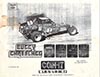
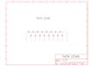
Continuing on with the Buggy Challenge repair.... well well well.... looks like the mystery might be solved. There's an inter-connect board
missing. Check the (bad quality, blurry and small) pics below. The connector G1 is likely joined to the 44-way connector where the RGB lines
are. Follow the traces up to connector C and you'll see 3 resistors R10, R11, R12 (marked in red). On the back they are connected to a large
trace, probably ground. I bet those are the RGB pull-down resistors hehe!
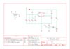
This page from the Buggy Challenge Operation Manual confirms it.... they used 470 ohm resistors hehe!! So yeah I was right LOL! It turns
out that connector E is the RGBS input from the main board and those traces go from connector E to G1 then to the monitor. The 470 ohm
pull-down resistors are tied to the same traces. If you squint really hard you can just see that the resistor bands are yellow, purple and
brown which equals 470 ohms :-D
And here's the Taito Buggy Challenge Conversion Kit Operation Manual pdf. This isn't on tamdb.net so if anyone has access to that site this
should be uploaded there. The inter-connect board is actually called the Relay PCB in the manual.
20th November 2022
Continuing with the Buggy Challenge repair, I'm wondering what happens when I power on without the 1530D resistor array. So I tried it as-is
and also by shorting pin 10 to ground.
Without it the sky is cyan but there's still a hint of banding. When shorting pin 10 to ground the sky is a darker blue and again with a
faint hint of banding. Note the banding is very subtle and not visible in the pics.
It turns out that the same 1530 resistor array is also used connected to the sound board YM2149 audio chip outputs but those only have 4 resistors
each so they are called 1530A.
I wired up the sound board and it appears to be working but sound only comes out of speakers 2 and 4. Speaker 1 is dead and speaker 3 has a
very very low volume. The 4 test points all have sound coming out. Incidentally all 4 speakers output exactly the same sound. It's basically
just mono but coming out of 4 speakers hehe! I isolated each speaker and wired it separately and it looks like the amp for left front and
left rear are bad as they were burning hot. I will have to order some MB3731 / MB3733 amps and change them later.
The sound board schematic is not 100% correct. Well the actual schematic is ok but the board layout shown is the smaller 2 speaker version.
There's a comment in the MAME source that the schematic is for an unreleased game. That's incorrect, it's simply for the 4 speaker version
which is the board I have here :-)
There's a few other comments in the MAME source that are incorrect.... - The gradient sky is completely wrong - it's more of a placeholder to show that it's supposed to be there.
Actually I was told that the gradient is fine and skews just like the real hardware :-)
Playing it in MAME shows it looks fine so not sure why that comment is there. It probably just needs to be removed (MAME source code is full
of old comments that need updating). - Stage 2 is supposed to have a different gradient, how/where this is located is unknown (pen 0x20?)
The 2nd stage does not have a different gradient as far as I can see.
So I went over the boards again for 1 whole day looking for bad logic chips to try to resolve the blurring issue but I didn't find anything
bad. I have seen similar faults in the past and it kind of looks like a missing video ground or a signal that needs to be tied to ground or
vcc that isn't connected. I think the best idea for now is to make a video of the game running from start to end as a reference then test
the PCB in the cabinet and see what happens. Additionally the wheel (connected to joystick left/right) doesn't register turning to the left
but right works ok. These left/right signals come from an optical sensor using a segmented encoder wheel (a bit like a spinner or trackball
sensor) which sends high pulses to pins 4 and 5 of a 74LS193 Synchronous 4-Bit Up/Down Binary Counter at IC46. I manually provided high
pulses to those pins and the wheel position moves in test mode so it appears to be working. It's better to test the whole thing in the cab
with the proper harness, proper controls and proper monitor.
Here's the video. I don't have a working wheel but I can correct the direction moving right (sort of) so the car is moving randomly but you
get to see the entire game. Of course this has both 'no collision' and 'no fuel loss' DIP switches set on otherwise it would be impossible
to play it without the proper controls. As far as I can tell the only real difference with the 4 speaker cockpit version is the ending music
is different. Other than that it's basically identical to the 2 speaker version. The sound ROMs are different but the main board ROMs match
the existing Taito Buggy Challenge romset.
Update - 21st November 2022: I was playing around today and noticed that the bluring affects everything and all colors. The fault has
to be on the output stage, right? I started randomly shorting the resistors and diodes in the RGB output section on the top board and when I
shorted D1, D2 and D3 the blur completely disappeared! I soldered a 75 ohm resistor across each diode and tested and it is basically 100%
other than the sky is missing. The strange thing is this is somehow affecting the sky gradient circuit on the bottom board. Blue must
still be there as I have white text.... with RGB color on a monitor Red+Blue+Green=White. The sky gradient is still there it's just very dark
now. But look on the bright side.... now my friend has a **SUPER RARE** Buggy Night Driving Challenge! Heheh!
Maybe those diodes are leaky. Except for the sky it now looks exactly like MAME! also notice in MAME that the text on the left is closer to
the left edge of the screen. This is a screen size and/or positioning error in MAME that needs to be corrected.
Update - 24th November 2022: With the diodes on the bottom board lifted at one end the blue sky disapears but the blur is still there.
This means the fault is NOT on the bottom board. But it looks like it might be fixed, or at least close enough to fixed. I kind of had
the right idea when shorting the diodes with resistors, but the values were too low. An engineer friend suggested I short the outputs to
ground through a 150 ohm resistor. That made the entire screen too dark. I played around with different resistor values. 820 ohm didn't
affect it at all and 150, 220, 470 made the colors too dark. When I shorted the video outputs to ground through 620 ohm resistors the blur
has basically gone and the colors are still there.
It looks like the colors might be over-driven for some reason but at this stage I'm not going to worry about it. I'll clean up the resistors
and put them on the back side of the board and that should be it. This really needs to be tested now in the cab.
Note the video above has been updated to show the fully working version.
19th November 2022
A local friend recently picked up a rough looking Taito Grand Champion cockpit cab that has been converted to run Taito's Buggy Challenge
and was sitting in a shed for probably 30 years. I believe my friend is being booked into psychiatric rehabilitation as I write this
hehe!
The boardset uses 3 boards with a separate sound board. This game is said to be some sort of 'official' upgrade path for a Grand Champion
cab. There's a flat cable connector that plugs into the 7-segment LED score display on the Grand Champion so that the display works even if
it's not really required. The board is complete, mostly untouched and even better this is the 4-speaker version which is not dumped!:-D
Like a lot of this old stuff it's not working. Fortunately the board uses only off-the-shelf parts so it's definitely possible to bring this
back from the dead. I wired up 5V and ground, powered on and checked the main Z80 CPU on the top board. The reset is there but the clock is
missing. There's also no clock on the 68705 microcontroller. There's only one crystal on the entire boardset, a 48MHz oscillator located on
the middle board. The top of the middle board shows one chip has been changed near the crystal (suspicious!) and there's some black
stuff on a couple of ceramic caps. The bottom side looks... um... interesting LOL!
Looks like some cowboy has been here before and messed with it..... urgghh!
My best guess is the power connector on the middle board was plugged in backwards and the board got 12V through the 5V line. The connectors
are keyed so no idea how that could happen, but never underestimate the skills of a cowboy LOL! I'm not sure just 12V would do this kind of
damage so maybe a higher voltage caused it. First I need to remove the chip and the hacks and see what's going on underneath.
Hmmm ok so basically there's nothing remaining hehe! Now if you look at the previous hack it's wired like this....
Pin 1 tied to pin 7. Pins 3, 4, 5, 6 & 8 tied together. Pins on the other side of the chip are still there. On the top side pin 1 is
connected to pin 16 (+5V but only just) and pin 2 is connected to pin 2 of the 74ALS04 at IC2. That's all.
Now look more closely.....
Pin 10 has a tiny bit of trace connected to it. That pin goes.... erm.... somewhere.
[deep breath] OK, let's have a look at the datasheet for the chip that was in the socket that I removed. It's a 74LS163....
The first page isn't much use other than telling me what the signal name is.... ENT. The typical application page shows that pin 10 is an
enable pin (Enable T) and is high when enabled and low when disabled. I'm assuming it would be enabled in this circuit so that pin needs to
be tied high, and the other pins need to be wired up properly. I cleaned up all the black stuff on both sides and wired up the chip
properly....
I first just powered on the middle board by itself and checked the clock output and now it's there. The 74LS163 and connected 74LS04 have
correct clock outputs on them. Great! Now I need to make a wiring harness with power on each board and a 44-way connector for the video and
some controls. After some hours that was done.
And this is the first power-up....
Wow! It's mostly working!!!
I found the pinout on the net and compared it with my wiring and it's correct. But the colors are bad. I swapped all the RGB wires around in
various combinations but no combination would produce the correct results. Hmmmm. Looks like green is missing but it's not totally dead
because with my logic probe I can see some sort of signal on the green pin. Maybe it's time to look for the schematic. The game is
pretty rare now in 2022 but by pure luck the schematic is available. It's readable but the top and bottom 1/4" has been cut off. There's
always something. What is it with people and schematics, do they all have half a brain or what? Grrrr!
I suppose it's better than nothing. Let's have a look at the video output circuit....
The green pin on the edge connector shown as (G-H) is connected to a 74LS367 at IC63 which is fed by a 74LS174 at IC64. The board has
previously had all the ROMs and RAM checked and it was all good other than one 6116 SRAM that has already been changed. Looking at the board
shows IC64 is our old friend the Fujitsu logic chip! I piggybacked a known good chip on top and powered on...
This looks pretty good now and some people might think this is fully fixed. Not really. The screen is too bright and most of the text at the
top is unreadable. Going into the test mode shows that all the text has a blur above it.
The bottom board has a pot to adjust something. Turning this makes the screen slightly darker but it flickers dark and light. The schematic shows this as 'VR' with a value of 10k-ohm.
To measure a pot check the resistance between the two outer pins. It measured about 7k. I turned the pot fully and measured from center pin
to edge pin and it is about 7k. The other side between center and the other edge pin measures around 700 ohms. Touching the pot makes the
screen flicker. A pot basically divides the resistance so on a 10k pot if one side measures 6k the other side should be 4k. With the pot
turned all the way to one side it should measure the value of the pot and the other side should be a few ohms so it looks like the pot
might be bad. I don't have the correct type but I found something that is the same value (10k) so I swapped that over. Now turning the pot
makes the screen go darker and the text is *almost* readable with the pot turned all the way to one side.
I might try to source a correct pot later but the reality is it probably just needs to be turned all the way down so wiring up a 50-100 ohm
resistor wll do the same thing. The text on the test screen has the blur on top so there's still a fault somewhere. The middle board is
called the OBJ board (OBJ=sprites) and the bottom board is called SCN (screen). I looked over all the boards and there's a bunch of Fujitsu
chips, luckily not that many (~25) and limited to 74LS139, 74LS157 and 74LS174. Because the boards need to be plugged in to work it's near
impossible to probe the board with everything connected together. My only option is to remove all the Fujitsu chips and hope that fixes it.
They all need to be removed and replaced anyway because they will fail sooner or later so I might as well just do it. A few hours later that
was done. Powering on showed no improvement :-/
I'm guessing it's probably on the bottom board but this kind of subtle video fault is very tricky to figure out. It could be on the final
video output stage on the top board or anywhere else in between. I need a break from this so I suppose now I can play with it a bit and try
to figure out some stuff to improve MAME. I also need to hook up the sound board and test it.
According to a comment in the MAME source code, the background sky gradient effect is close but not correct in MAME. This is generated by
the circuit shown in the bottom right corner of the schematic page shown above. Basically it only effects green and blue and is adjusted by
that 10k pot. There's 8 bits of data on the SLA bus (SLA0..SLA7) going into 2x 74LS193 4-bit binary counter chips which output into a
74LS374 Octal D-Type Flip Flop chip at IC77 that outputs 8 bits of data and is weighted by some (unknown) resistors on the outputs. These
are inside a custom resistor array package marked '1530D'. This is actually an R-2R DAC. That data gets merged by the DAC then outputs to
the 10k pot, goes through a transistor and some diodes then merges with the existing green and blue data at the flat cable connector R. When
I touch the resistor array, diodes or transistor I get an exaggerated gradient effect on screen.
I desoldered the resistor pack to measure it.
Pin 1 is tied to ground (chopped off on the schematic).
The resistance measurements checked at the resistor pack pins are....
pins 1-2: 45.1k
pins 1-3: 60.1k
pins 1-4: 75.1k
pins 1-5: 90.1k
pins 1-6: 105.1k
pins 1-7: 120.2k
pins 1-8: 135.2k
pins 1-9: 150.2k
pins 1-10:120.3k
There are only 8 connections on the 1530D tied to chip 77, pins 2-9 on the resistor pack are tied to chip 77 pins 2,5,6,9,12,15,16,19 in
that order.
Pin 10 is the final output pin and is tied to a 4.7k resistor then to the 10k pot marked 'VR'.
Pin 10 of the resistor pack is also tied to the base of the 1815 transistor.
The resistance between each pin is....
1-2: 45.1k (same as above)
2-3: 75.1k
3-4: 75.1K
4-5: 75.1k
5-6: 75.0k
6-7: 75.1k
7-8: 75.0k
8-9: 75.0k
9-10: 29.96k
This gives the final result (shown in schematic form)....
Taking into consideration measurement rounding errors and accumulated measurement errors (+- a few ohms on each resistor), now the part
number makes sense.... 1530.... it's comprised of 8x 15k resistors and 8x 30k resistors. Simple! :-D
This should be more than enough information to be able to correctly hook up the sky effect gradient in MAME.
13th November 2022
Now that we have a good dump of Alpine Surfer I thought I would have a look at my Alpine Surfer and try to resurrect it. The main board
works when the newly dumped ROM board is swapped over so I know my CPU board is good and the fault has to be on the ROM board. Since the old
dump didn't work in MAME at least one of the ROMs must be bad. I pulled all the old ROMs off my board and replaced them with new flash ROMs
programmed with the new dump.
It didn't work! WTF!!???
Now the eagle-eyed reader might be thinking there's one trace missing so that's why. Yes one pad on ROM 4 came off but it actually doesn't
matter. This is a common issue with TSOP48 ROMs of this kind. The 2 outer pins on all 4 edges (8 pins total) are not connected to anything.
The pad is very tiny and the glue holding the pad on can fail when heated and the pad comes off easily. It's no big deal so don't worry
about it. I went over all the solder joints but they were all good. I thought maybe the PAL could be bad but considering the board hasn't
been powered up for over 18 years that's unlikely. I decided to trace the board with my multimeter and check all the connections from the
ROMs to the edge connector and also that all the ROMs were joined to each other. I couldn't believe it... one pin on ROM 5 wasn't connected
to the other ROMs. This is pin 15 which is A11. The address lines should all be connected together but pin 15 had no connection to the other
ROMs! There's no damage on the board so it's a mystery why that pin is not connected but I suspect that might have been the original fault.
I joined that with a tiny micro-wire, tested it and it works hehe!
Next I re-read all the old ROMs again just in case. They all came up the same as my previous dump but this definitely doesn't work in MAME.
I'm curious which ROM or ROMs are bad. I erased all the ROMs and tried to re-program them and ROM 4 would not verify. Ah! So that's the bad
ROM! All the other ROMs programmed and verified ok so this makes me think that the other ROMs are actually ok. I was talking to my local
friend and he said he found another AF2 Ver.A ROM board and I could borrow it if I wanted to dump it. So I grabbed that off him and read all
the ROMs. After doing that I found that the ROMs match the old dump!!!! All except ROM 4 which was different. I plugged these ROMs into MAME
(the old dump but with ROM 4 changed to the different ROM) and I couldn't believe it, the game works! So there's actually 2 versions of AF2
Ver.A. I suspect one is Ver.B but the Namco guys either forgot to update the date and time in the code (which shows in test mode in
'OTHERS') or they just couldn't be bothered, or maybe it was a serious bug and they wanted to hide the screw-up so left the version the same
and hoped no-one would notice. Oops! One person did heheh! This other version should be added to MAME as an alternative version but no idea
what's actually different.
While I'm looking at old jobs I decided to pull out a non-working IGS PGM board that was missing the main graphics chip (custom IGS023
chip).
If you've been following over the years you'll remember this PGM board was bought for parts for a repair and the chip was taken to repair
a Cave Do Donpachi Dai-Ou-Jou board that had a mangled and corroded chip. I kept that chip in the hope that it was still ok and that the
only issue was those mangled PCB traces that I fixed up all those years ago in December of 2018. Here's a quick refresher pic...
For those new here, yes, believe it or not I actually fixed that board by removing the chip, tidying up the PCB traces, patching the damage
with micro-wires and replacing the chip with one in perfect condition. Check the site history from 2018 here
for more details if you missed it.
So hmmm, I had this old damaged chip here and a working IGS PGM main board but with that chip missing. Did the chip work? Could I fix it?
Only one way to find out. I spent about 2 hours prodding at the chip legs, scraping the legs with a sharp knife and cleaning the crap off
them and carefully straightening them as good as I could. It wasn't perfect. 3 of the sides were very good but the hammered side was still a
bit rough but it would be nearly impossible to make it perfect. To add to that the main board was a bit corroded in the battery area but
hopefully none of that matters. I went with what I had and re-attached the chip which took about
1 1/2 hours.
Then powered on...
Holy shit it works!!!! Hehehe!!!
There's some vertical lines in the graphics. In game it's almost perfect other than some lines in the background graphics. Looks like 2
lines. This might not be that hard to fix. Looks like I just need to go over all the rough-side pins again and check for loose pins.
Yup! that was it, just a couple of loose pins that were a bit corroded still and didn't want to take solder. Some extra scraping, flux and
resoldering solved that problem and now it's working 100% perfect hehe! Wow! I can't believe it :-D
I suppose I should fix up the corrosion too. The corrosion has gone through some vias too. Urgghh! I removed all the parts so I could get a
good look at it.
Someone had removed the nicad battery (a good thing) and replaced it with a coin battery holder but didn't clean up under the battery. Wow!
What a loser LOL!
It looks a lot worse than it is. After a clean up and scraping all the traces to remove the corrosion and poking through the vias with a pin
to clean it up I found there's actually no broken traces. Lucky!! I initially tried some lemon juice but it didn't do anything so I had to
scrape all the traces with a knife. There's no need to put back the solder mask. Noobs often replace it with some sort of UV solder mask
b.s. because they think they have to and it somehow affects the operation of the board. This is so far from the truth it's hilarious. All it
does is prevent solder sticking to areas of copper that shouldn't have solder on them and causing a short when the board is wave soldered
and assembled at the factory. After that the solder mask does nothing and there's no need to replace it. If you do, all you are doing is
making the next repair job more difficult. I tested the toggle switch with my multimeter and it still works (this just clears the backup RAM
as far as I know) but the test button switch is stuffed and doesn't work. I replaced the old parts and a new test button. I powered on and
tested it and everything is working great. The traces in this area and those other parts (the resistor packs etc) are only used for the flat
cable connector. That connector is used for the mahjong panel which I'm not going to use so none of that stuff matters.
12th November 2022
Back in April of 2004 I dumped Alpine Surfer which is a Namco game from 1996 running on Super System 22 hardware. It's the same board that
runs Time Crisis, Dirt Dash, Tokyo Wars, Alpine Racer, Prop Cycle, Cyber Cycles and a couple of others. The system is very powerful and
comprises 4 boards plugged into a motherboard containing only slots. The board we got hold of was in unknown condition and didn't work when
I tested it on my SS22 test rig. I could only hope the issue was elsewhere and that the ROMs were good. Over the years various attempts were
made to get the emulation working but no one ever got it fully working. Forward 18 years and 7 months to yesterday and it was discovered
that the dump was corrupt. This isn't surprising as the program code is held in 4x TSOP48 Fujitsu flash ROMs which go bad just looking at
them. Like Superman I sprung into action and was able to locate another board owned by a local friend who keeps a stock of these boards to
repair Super System 22 games still being operated. Luckily he had another Alpine Surfer board (same revision AF2 Ver.A) so I borrowed it,
dumped it and a few hours later the new dump was updated in MAME. The emulation is now working and the game is playable. This is pretty
amazing and really lucky considering that it's highly unlikely any working cabs are out there now. The game isn't that bad but it plays more
like a kiddie ride. No matter how well you do the race is over after getting to the bottom of the hill. There's no 2nd track with increased
difficulty, that's it game over! I would have been pretty pissed off if I had paid $2 to play this and the game only lasted 1 minute and 30
seconds then game over. Probably explains why it wasn't a popular game and they are all extinct now. Aside from that, Fujitsu made damn sure
that none of the games using their ROMs and logic chips are working now hehe!
There are some missing effects in the emulation so I made a reference video of me playing it for a few minutes. Surprisingly it works with
my Dirt Dash control set-up after it was re-calibrated for Alpine Surfer and works very well. So well in fact that I even got a high score
and showed one of the missing effects on the high score entry screen. One of the other missing effects is on the READY / GO screen and the
other one I know about is incorrect transparency on the SELECT GAME MODE screen.
Here's a few pics from MAME and a video of the game play running on real hardware.
27th October 2022
I have an old Mortal Kombat II ROM board that's been lying around for years in unknown condition. Back then I didn't have a working MKII
main board so I couldn't test it. If you've been paying attention you'll know I recently fixed an MKII mainboard so now it's time to look at
this spare ROM board.
The parts side is near perfect but unsurprisingly the top side looks pretty rough and might have some damage that most likely happened years
later while tossed on a junk pile before it came to me. I first checked the scratched area but it turned out to be fine. I plugged the board
in and the whole board was not working and it even messed up the ROMs on the main board!
Everything comes up as bad which is impossible as there's no way every part is bad. If I press a button to let the test end and go in-game,
it shows a scrambled 'MIDWAY' logo then resets. One of the 244 buffers could be bad but they wouldn't all be bad so some of it should pass the
test. It's more likely the enable signal is missing but this doesn't explain why the main board ROMs also come up as bad. I probed the 244
enable pins (1 and 19) and there's no signal on my logic probe, nothing at all, no low or high, nothing! It should be low. The schematics
show these pins are all connected together and are tied to a 100 ohm resistor then to ground.
I confirmed the chips are connected to the resistor and the resistor measures 100 ohms. The resistance between power and ground is around
150 ohms so it looks like there's a partial short on the board. On my working board it is several mega-ohms. I removed all of the
electrolytic capacitors but there was no change to the resistance. The small yellow ceramic capacitors are not polarized and generally don't
go bad. The only parts remaining that are likely to be shorted are the logic chips. To speed this up, the easiest way to figure out which
chip is shorted is to disconnect the ground pin. Don't do like noobs do and cut the pin off the chip on the top side because that just
causes issues and also looks really sloppy! Simply desolder the pin and push it until it is no longer touching the hole.
After doing that the resistance between power and ground has gone way up and the short is gone. I checked all the logic chips individually
between pins 10 (ground) and 20 (power). Two of the chips have no connection (which is correct) and the other one has around 150 ohms...
bingo hehe! I removed the chip and tested it in my chip tester and it failed. I was going to replace it with another identical chip I
found in my parts bin (74ACT244) but that one also failed in the chip tester and it was even worse than the original chip!
I replaced the chip at U3 with a 74F244. I don't have the original part 74ACT244 but I suspect LS244 or HCT244 will also work fine. I
powered on...
Problem solved :-D
So even though the ROM board looks like crap it actually works fine. The problem was just one shorted logic chip hehe!
Keeping with the same theme, the next thing I wanted to fix is a spare but not-working Mortal Kombat II sound board.
This one also looks a bit rough LOL! There's a couple of parts missing... the power amp and the 10MHz crystal.
I replaced the crystal expecting it to spring to life.
Unfortunately there was still no clock on the ADSP2105 sound chip. Since everything was a bit rough looking I pulled out all the EPROMs,
cleaned the legs, read them with an EPROM programmer and compared them with MAME ROM archives. They matched 100%. I replaced the ROMs but
still no change. I pulled out the ADSP2105, cleaned the chip using some 400-grit sandpaper and also cleaned the socket then replaced the
chip.
Now the LED is on! This isn't just a passive LED it gets its signal only when the board is active. Now I just had to replace the missing amp
and hopefully it would work. I didn't have the original part because all the spares I had were used recently in another sound board repair
marathon a couple of weeks ago (keep reading....). But I know the MB3731 is pin compatible with a MB3733. The only difference is the 33 is 20W and the 31 is 18W. The MB3733 is
commonly used on Sega System 16 boards and I had one here that was toasted and only good for parts. I pulled the amp off and fitted it onto
the sound board, plugged everything back in and that fixed the sound board fully. I don't have a heatsink for the amp but they actually
don't get very hot so it isn't 100% required. This is just a spare board so I can easily fit some sort of heatsink later.
So the original fault with this board appears to have been just an oxidized PLCC68 socket LOL!
Keeping with the same theme again, if you've read the recent NBA Jam repair logs below you will have noticed I did not mention anything about
sound. This is because at the time I didn't have any sound boards. This changed recently when a local friend gave me 3 non-working and
partially stripped sound boards. Two are from NBA Jam and one is from Mortal Kombat. All the boards are identical except the NBA Jam boards
use a MB3731 sound amp (same as MKII) and the Mortal Kombat sound board uses a totally different amp chip. Regardless, the two types of
boards are functionally and electrically compatible and interchangeable between these two games.
This board is missing several parts.... 6264 static RAM, 6809 CPU, 3.579545MHz crystal, OKI M6295 ADPCM sound chip, AD7524 DAC and the main
power amp MB3731. The first thing to do is check for trace damage (there was none) and replace all the missing parts.
I powered on and in the test mode the Sound IRQ check passed but there was no sound.
I went back to game mode and checked for activity on the CPU, ROM and RAM and the board was definitely running.
The YM2151 and OKI chips were also active. Let's check the schematics.
The output from the YM2151 pin 21 (SO, Serial Output) goes to a YM3012 DAC at U28. The outputs from there go to a LM324 at U29. The outputs
on the LM324 are on pins 1 & 7. At that point the sound is analog and can be heard with a logic probe that has a built-in piezo speaker.
There was no sound on those pins. The YM3012 had active inputs but the outputs were not active. When working the YM3012 outputs audible
analog sound on pins 9, 10, 11 & 12. There was no sound on the logic probe when checking those pins. I piggybacked the YM3012 with a known
good chip and now I could hear music so I swapped out the faulty YM3012 for a working chip.
Tested again and now the sound board is fully working. So the original fault was just a bad YM3012 DAC hehe!
The 2nd board is in similar condition but is originally from Mortal Kombat.
This one is missing a few more parts than the previous one.... 6809 CPU, all ROMs, OKI M6295, 3.579545MHz crystal, one connector, the PAL,
YM2151 sound chip, AD7524 DAC, YM3012 DAC, AM26LS31 (x1) and AM26LS32 (x2). Wow hehe!!
The YM3012 and AD7524 had empty sockets there so I plugged those in before taking the above pic.
Note pay attention to the orientation of the AD7524 DAC.... it's positioned backwards compared to all the other parts ^_^
So here we go again... replace all the missing parts. All the parts in sockets I simply took from the board I had just fixed since I knew
those parts are good. The AM26LS31/32 are strange parts that can't be easily tested so I pulled them off my working board and put them on
this board. Luckily the main power amp was there since it was a different type that isn't useful for fixing NBA Jam sound boards.
I powered on but there was no sound.
I touched the amp with a wet finger and there was no popping sound. I checked for 12V on the amp and it was missing! I had previously
replaced the missing connector with a new one I had lying around. I checked that connector and there was 12V going in but nothing coming out
of the connector??? It's just wires and solid traces WFT?? The 12V should also be present on the nearby coil but again nothing. I pulled the
connector off and had a look underneath.
Ah right!!! The connector was previously removed... erm... let's just say 'not very well' hehe! The vias have been ripped out and so
the power isn't getting to the trace. I added a wire through the hole and soldered it on both sides then replaced the connector.
On power up I can now hear the start-up 'bong' sound. The board appears to be working but not quite perfect. Some of the sounds are
distorted slightly. This could be caused by any number of parts, TL084 op amps, LM324 op amp, both DACs, MC3340 electronic volume chip or
maybe just bad caps. Looking on the bottom it's clear some of the caps have previously been changed but again, not very well. I pulled all
of those caps (the green ones) and tested them with my component tester and they were all within specification so I put them back. But
before doing that I patched the vias like before because the vias were pulled out just like the 12V connector vias hehe!
The other black caps near the amp were also pretty nasty looking and appear to have leaked too. So I pulled and replaced them. I tested them
later and found 2 of them were out of specification. Not surprising as they are all cheapo Chinese 'Suntan' brand. You can tell they are
crap just by the name hehe! I also patched a couple of the pads as they were eaten away and missing.
I tested the sound and now it works fine without any distortion. Due to all the missing parts it's hard to tell what the original fault was,
but I suspect it might have been one of the parts that was removed because there wasn't anything else wrong with it other than some bad caps
and that would have happened many years later after it had already failed and was tossed aside. So pay attention to the list of parts that
have been removed on all these boards I'm repairing in this log. If you have a NBA Jam sound fault chances are it's caused by one of those
parts ^_^
The 3rd and final sound board was in a similar state to all the others with a bunch of missing parts... 6809 CPU, program ROM, the PAL,
3.579545MHz crystal, 8MHz oscillator, one axial electrolytic cap, a diode near the missing cap, AD7524 DAC, OKI M6295, MB3731 power amp and
a Motorola MC3340 electronic volume chip.
Same story again, check the traces for damage then replace all the missing parts and temporarily use the parts in sockets taken from the working
boards. I replaced everything except the MC3340 (I don't have a spare) and the diode. Additionally there was a missing pin on the flat cable
connector so I replaced the pin taken from a new pin header strip. I also put back a bunch of resistors that had one end lifted. No idea why
anyone would do that LOL!
The missing diode might be an issue but for now I just powered on to test it without the diode and MC3340. There
was no sound. The 12V was present on the amp and touching it with a wet finger produced a pop sound. The CPU, ROM and RAM were active so it
looked like the board was running. I really need to find out what that diode does. Let's look at the schematics again...
Hmmm.... the diode is a 1N5232 5.6V zener diode. I definitely don't have one of those in stock. It has 12V on one side and the zener
connects to ground on the other side so this is a crude way of regulating the voltage going into some of the pins on the TL084 op amps. On
the working NBA Jam sound board the voltage on the TL084 op amp pins 3, 5, 10 and 12 measures 5.7V which then comes out on pin 8 as signal
'AUX OUT' and then feeds into pin 1 on the MC3340. Uh oh! Hmmm so I need to replace that chip for sure. Ok I pulled the chip from one of the
other boards and fitted it into a socket. Later I'll replace it on the other board with a new part if I can get one. Hmmm so this diode is
still a problem. I suppose I will have to borrow one from the other board. I picked up one of the boards I just repaired and it just
happened to be the Mortal Kombat sound board. I checked the position where the diode is and there's no diode?? In this place is a resistor
at R65. WTF??? Let's check the MK sound board schematics....
So it's basically the same circuit but the diode is replaced with a 100k resistor. OK, so I'll put a 100k resistor on the board and see what
happens hehe!
I powered on and there's still no sound. I measured the input pins on the TL084 and the voltage is 12V! Eh? Ok back to the schematics again
LOL! Oh I see now, the 12V goes through a 100k resistor too! So there's 2x 100k resistors at R54 and R65. On NBA Jam the resistor on the 12V
input (R54) is 200 ohms but of course the zener diode CR2 regulates the voltage to ~5.7V. I checked the sound board and didn't find R54. It
must be somewhere?? After checking for many minutes I found it was partially hidden under a sticker hehe! Ok so I changed R54 to 100k,
powered on and now there's sound and it's perfect!! The voltage on the TL084 inputs is ~6.0V which is close enough to the original 5.7V
The pic below shows the two resistors that have been changed are the 5-band type with blue base color at locations R54 (near Midway Games
sticker) and CR2.
Problem solved :-D
So if you ever have a NBA Jam sound board with a bad 5.6V zener you can just replace CR2 and R54 with 100k resistors and that will fix it :-)
As for the original fault on this board, that's unknown. With so many removed parts it could have been any one of them. But for sure it
wasn't any of the remaining parts because the board worked fine by just replacing all the missing parts.
The final minor issue is I need to sort out the missing MC3340 chip. The use of this chip seems a little bit odd because there's no way to change the volume from
within the test menu. On Mortal Kombat 3 you can go into the test mode and change the volume 'electronically' but on NBA Jam and Mortal
Kombat you can only change the volume with the volume pot so it's strange why they used this chip. Let's have a look at the datasheet...
and the schematic....
It shows the input on pin 1 and output on pin 7. Pin 7 is tied directly to the input of the main power amp so without the chip the sound
can't get to the amp. The chip runs on 9V which explains why there's a 7809 voltage regulator next to it. Hmmmm. I wonder what happens if I
remove the chip and then short pin 1 and 7 hehe!! So I did and powered on and the sound still works LOL! So this bullshit chip isn't even
needed. I'll do some more testing later but for now I will leave it like this and it should be fine.
The other small modification that should be done anyway to all of these boards is to put a 4.7k resistor between pins 2 & 4 of connector P5.
This normally goes to a volume pot on the end of a small cable about 30cm long which plugs into connector P5. You can see that in the
schematic above showing the MC3340. A lot of the time this cable is missing and without it there won't be any sound. Adding a resistor means
you don't need the external pot and since you are using the board in a cabinet you can simply adjust the volume using the cabinet volume
pot. Here's a pic showing two examples of where the resistor can be soldered on. Basically just tie pin 2 to ground through a resistor. I
did this mod to all of these repaired boards before even beginning to repair them so I didn't have to worry about this problem :-)
22nd October 2022
Here's a few more repairs I did recently.
Sega Model 2A Dead Or Alive
I've had this for many years but never really looked it it. The game was working fine for a few minutes then it would glitch and show only
garbage on screen or freeze and show only the background with the music still playing. Looking closely that the board showed that one of the
custom Sega DSP chips was rusted and one leg was disconnected flush with the plastic package of the chip. The leg next to that one was just
about ready to fall off too.
This is unfortunately very common to see on boards that have been operated in arcades near the coast (which is nearly all of them here in
Australia) as most arcades just run boards into the ground (zero maintenance) then toss them and buy the latest game since they are making
huge sums of money per month. In some cases it's less than 1 year from new to being rotted
out and unrepairable hehe! The people running these arcades are too stupid to realise that a little bit of preventative maintenance would
make these boards last even longer and they would make even more profit LOL!
Anyway, the rusted pin goes to a nearby SOP40 mask ROM on pin 20 which is D11. This can be fixed two ways, either grind
away the plastic and attach a micro-wire or replace the chip. The chip was in pretty rough condition anyway so I opted for the 2nd choice
because for me that's quicker and easier and likely more permanent too. Plus my skill set includes this kind of job without breaking a sweat
so it's no problem for me to swap over the chip. I had a junk board here with the same chip so I removed it and after an hour the task was
done and on powering up the problem was fixed.
The soldering on the chip is now better than factory too so this chip will not come loose like many others do. If you own any Model 2 games
be very sure you keep the board clean and dry and probably put some heatsinks on the hot chips too for good measure, just to be safe.
Definitely don't try to run these boards without the original metal box (with lid!) and fans as all you are doing is shortening the life of the custom
chips.
The other main issue with these Sega boards is open vias at random locations and it can happen on any of the boards (ROM board, CPU or Video
board). The vias are really tiny (<0.3mm) and there's probably some kind of manufacturing defect because this is why most Model 2 and Model 3 boards
die and unfortunately there's not a lot can be done to prevent it as they will all die no matter how well you take care of it. So best to
play and enjoy these games while they work because once they get the dreaded via rot they will be near impossible to fix.
Psycho-Nics Oscar
A local friend asked me to look at his Psycho-Nics Oscar which wasn't showing anything on screen. This might not be that difficult because
there are a bunch of Fujitsu logic chips. I went over the board and removed most of the Fujitsu chips and replaced them with good chips but
there was no change. The CPU appeared to be working as there was clock, reset and activity on the address and data pins. I pulled all the
ROMs and RAM and checked them but they were also ok. There's also a Fujitsu MB7124 bi-polar PROM. This has something to do with enabling the
layers and priorities. I checked the PROM in my eprom programmer and it was bad! It is compatible with 82S147 but I didn't have a spare so as
an experiment I custom-wired up an eprom and powered on....
Hehehe!!! It seems to have fixed it but not quite. Looking closely at the title screen shows a band that is cross-hatched. There's a similar fault on
some of the sprites. This might be caused by the EPROM being too slow so my friend decided to splurge out on some original PROMs (which are
getting VERY expensive now). In the meantime I pulled the remaining Fujitsu logic chips and replaced them but no change to the sprites. When
the PROMs arrived I programmed one and plugged it in but that didn't solve the problem but at least now the board looked clean and original
again hehe! The last thing it can be is the custom sprite chip. I don't have spares but my friend had a junk Data East Birdie Try which uses
the same PGA chip. This must have been an earlier release as most of the Birdie Try boards I've seen use a QFP chip. I pulled and swapped
the chip over and that fixed the problem :-D
Tekken 2
I got this junk board from a local friend for free. These are almost not worth fixing as Tekken 2 isn't the most exciting game hehe! But I like a
challenge so let's try to fix it. The game worked but had a very minor graphical fault. There were some tiny vertical lines on screen and in
the attract mode when the player was hit there were black squares, especially when the player hits the ground where dust/smoke appears.
The usual fault with these board is loose legs on the custom Sony chips and loose legs on the VRAM but in this case normally the graphical
faults are much worse so I didn't think this was the issue. I reflowed all the chips but there was no change on screen. It doesn't hurt to
reflow all the chips on the CPU board anyway as the soldering is really terrible and often the main cause of faults on Namco System 11
boards. Another fault if the board is dead it can be cracked solder joints on the 8x SOJ32 RAMs. This is the main program RAM so if there's
any fault with these chips the game won't boot up. Since it was working and there were no loose legs it can only be the VRAM. These are very
special dual-port RAMs with 256kB x16-bit DRAM and also 512 byte x 16-bit Serial Access RAM. There's no easy way to check these so I simply
swapped each chip taken from a working board one by one and tested. This is by far quicker than trying to figure out which one is bad using
an oscilloscope. I had to change all 4 chips and it was the last one hehe! Just bloody typical. I should have changed the last one first
hehe!! So with one fixed I now had a previously working top board that was missing a RAM. I found another random ssop64 chip in my box of
spares but didn't know if it was compatible or good. I just replaced the chip onto the other working board for kicks and I knew the board
was previously working so this would tell me if the chip was good or not. I powered on and it worked!
The actual bad chip was IC25 but this kind of fault can be caused by any of the four VRAMs.
This information is largely undocumented so these are the RAMs compatible with the original chip....
SEC KM4216V256 (original chip)
NEC D482445LGW-A70-S
Toshiba TC52V4165SF-80
Last two are not documented as compatible and the last one has no datasheet available but now I know what it is because it works on the
Tekken 2 board :-D
Note KM4216C256 and KM4216C258 are pin-compatible but run on 5V so no good for this application. The correct RAMs are 3.3V only.
25th September 2022
A local friend asked me to look at his Sega SC3000 computer which was not working....
I opened it up and saw that the motherboard won't come out easily. The power connector is soldered to the input pins on the board and has to
be desoldered to get the board out (erm, great design Sega!). Once the board was out I checked the fuse which was good. I jumpered the power
pins together (since now the switch is missing) and powered on. The voltages checked ok (9VDC center NEGATIVE on the DC jack... same as Sega
Master System). There's no easy place to hook up the logic probe so I soldered some wires to a convenience place and probed a few things
with my logic probe. After some time probing around and not seeing anything useful I realised that there's no ROM on the motherboard (LOL!)
so nothing was running, hence no activity on the chips. I plugged in a cart, powered on and nothing happened. I checked the Z80 clock and
reset and they were present. I probed the CPU and RAM with my logic probe just to see if it was alive and some of it was active but it
didn't look correct. At some point I must have bumped the cart because I saw some activity on the logic probe but then it stopped again. I
wiggled the cart and the activity started and stopped as I moved it. I turned the board over and saw a bunch of cracked solder joints on the
cart connector. I re-flowed those with new solder and also re-flowed the 9VDC power input jack which also had cracked solder joints.
Now probing it showed proper activity! Maybe it was even working? I only had the crappy RF cable so I plugged that into my fancy Sony WEGA
32" widescreen CRT TV that I bought new around 2005, tuned it in but couldn't get a picture. It would kind of show something while tuning
it but only with the tuning screen up and it was rolling vertically. Most likely the RF modulator was stuffed but I definitely didn't feel
like repairing it because there are better ways to get a picture out of the SC3000. The PAL version of the SC3000 has a TMS9929 video
chip which outputs a kind of partial RGB signal so I hooked it up to my arcade monitor just to see if I could get any picture out of it.
Hmmm yeah ok, so it's working. I didn't have the proper composite cable to test it on a TV. By coincidence another local friend was coming
over a few days later so I asked if he could bring his SC3000 and composite cable so I could test the faulty one, which he did. Using the
proper composite cable I powered on but was surprised to see nothing on the screen! It made the correct power-up beep but no picture????
Since the computer is working the faulty part could only be on the little top board which is specific to PAL regions. Luckily I had the
other working SC3000 so I swapped over the daughterboard and it worked!! Hmmm, ok so now to diagnose where the fault is. I first checked the
schematic. The top right corner has the schematic for the PAL daughterboard....
It looks pretty complicated but you can ignore most of it. Always remember, you don't need to know how something works to fix it :-)
I checked the power input on the connector and it was 9VDC... correct. Pins 1, 2 & 3 are also active which is the video input coming out of
the TMS9929. The connector output pins 6 & 7 (COMP / RF) are dead, no signal there.
It's definitely not necessary to know how it works but for those interested I'll give you a brief overview just for your curiosity. If you
don't want to know, skip to the next paragraph. The power goes into T101 which is some sort of custom transformer (possibly made by Toyo
according to an engineer friend) and through some resistors and transistors. On the output (secondary winding) side of the transformer pin 5
provides feedback voltage to transistor TR106 and TR107. Pin 3 of the transformer goes through a diode D101 and inductor L104 then out into the
rest of the circuit. The little round transformer and the resistors, transistors and zener diode makes a boost circuit. TR107 dampens the
oscillator TR106 by shorting its base to ground when the DC output voltage on D101 exceeds the zener voltage (ZD101 11V) plus the TR107 base
emitter voltage (0.6V) so this is effectively a (not very good) way of regulating the output to about 11.6 volts. All the parts on the left
side of T101 make that happen. Without TR107 the oscillator will run wild and the output could be dozens of volts as there is no regulation
mechanism and without TR106 it won't do anything. The output AC pulses on pin 3 get rectified and converted to DC by D101 and caps C116,
C117, C119 so only from that point onwards is it DC and measurable as DC. When working, it's not possible to measure much DC voltage on pin
3 of the transformer because there should be equal magnitude positive and negative pulses above and below the ground rail so the meter set
on DC voltage reads the average which should read 0v or near to it.
The schematic shows the main chip is a LM1889 which is a TV-Video Modulator chip. This does the conversion from the strange Y, R-Y, B-Y
video coming out of the TMS9929 and turns it into a proper composite video signal. The datasheet says it requires 12V-18V to work. There
must be voltage on the right side of L104 since that connects directly to all the chips. Measuring that point shows no voltage so the
transformer wasn't outputting any voltage. Pins 1 & 2 of the transformer had 9VDC there so the input power was ok. I pulled L104 and it
checked ok in my component tester as a 0.01mH inductor (100nH as shown on the schematic). With L104 out of circuit it separates the
modulator from the 12V boost circuit. I checked the DC output at D101 and there was still no output so at least the modulator is not causing
a short and pulling down the boost circuit. If I had seen voltage there it could mean there was a fault somewhere in the main modulator
circuit. So the fault was definitely in the boost circuit. I pulled the diodes and tested them in my component tester and they checked ok. I
pulled and tested the transistors. TR107 identified as an NPN transistor (no need to worry about type, if it IDs as a transistor it's
probably ok). However TR106 identifed as 2 diodes and a resistor, which isn't correct!
This is a 2SC2001 transistor and not very common so I didn't have any spares on hand. An equivalent is BC639 but I didn't have that one
either. I tried using a 2N3904. While not really ideal it can be fitted by crossing over pins 2 & 3 and putting it in backwards and then it
will have the same pinout as the original transistor. It's probably not going to work because the 2SC2001 is a special class of transistor
called "Low VCE saturation" but I tried it hoping it would make some difference but there was still nothing coming out of the transformer.
At this point I had to give up trying to fix it and realise that the transformer was bad too. I'm thinking probably the transistor blew and
took out the transformer, or vise-versa.
So what to do next? Well the boost circuit just provides some sort of DC power to the modulator circuit. The zener regulates it to around
11.6V, at least on paper. If I hook up the correct voltage there directly on the right side of L104 I don't need the boost circuit.....
Hmmmm. Well I just happened to have reversed a boost circuit board a few days ago LOL!
Check item #7 on my R.E. page....
Of course this one came from China. You wouldn't actually make your own board because it's far cheaper to just buy them as they are only
AUD2.40 each. I only made the schematic to see how it works so I can add that to another PCB project I'm working on. Now I just needed to
know the correct voltage to inject. I powered up the other working SC3000 and measured the voltages. At C116 and the input side of L104 the
voltage is 11.56VDC and the output side of L104 is 11.34VDC. The same 11.34VDC is on all 3 chips. Measuring the voltage on T101, there's no
DC voltage on pins 3,4,5. The AC voltage at pin 3 is 1.65VAC, pin 4 is 0V and pin 5 is 0.32VAC. With L104 removed to isolate the boost
circuit (it MUST be removed otherwise the injected voltage will destroy ZD101 and TR107) I hooked up my little boost board. This board
outputs 12.4V but it's fine as-is since all the chips will work from 12V to 18V. The previous 11.6V was actually a bit low as the datasheet
for the LM1889 specifies the minimum voltage is 12V hehe! I wired the output to one of the logic chips directly (12V and ground) and I took
the input voltage from the connector pin 8 (+9VDC)....
I powered on and....
Yup! It works!!!
But the picture is really bad, wavey etc. I moved the 12V board away from the modulator and that made the picture a lot better, basically perfect.
I decided to remove the transformer T101 and TR106. When I removed the transformer it fell apart LOL!
That explains why it didn't work as pin 3 (11.6V output) has broken off the transformer. That little transformer might actually be
ok. The pin just came loose but it's only a pin. The transformer winding probably just came off so it can be attached to the pin. The pin is
just a pin it doesn't connect internally, that's what the winding goes to. But the SC3000 works fine now and I don't have a replacement
2SC2001 anyway so I will just leave it. I wrapped the little power board in some insulation tape and placed it inside the case with the
motherboard, reassembled it and that's the end of this repair.
UPDATE: 26th October 2022
My friend decided he wanted me to try fixing the transformer so I found a more common compatible type of transistor and he ordered a replacement BC639
transistor (BC639 is cheaper than 2SC2001). It arrived and I soldered the part into the board. I removed the little 12V module. Then I fixed
the broken leg on the transformer and re-soldered the winding wire coming from inside the sealed transformer which luckily wasn't broken
off, then soldered the tranformer back onto the board. I powered on and it worked!! So the only fault was a bad transistor at TR106. However
the transistor and/or the transformer is doing something else as now the colors are much more vivid than with my 12V module. So while the little
module works you'll end up with washed out dull colors. To fix it properly requires the transformer and transistor at TR106 as well!
Compare this next pic with the one previously shown and you'll see the colors are much nicer now :-)
24th September 2022
I can't say much about it right now (this isn't my project) but here's a first glimpse of Namco System 246 emulation.... and no this isn't
running in MAME and likely never will.... Update: Whoops, vids were set to draft/private and forgot to hit 'publish' hehe! Fixed now and
added Ridge Racer V too :-)
16th September 2022
Here's a follow-up on the other Ivan "Ironman" Stewart's Super Offroad Challenge and a couple more Midway T-Unit repairs....
Ivan "Ironman" Stewart's Super Offroad Challenge #2
The owner wanted a 2nd working boardset as a spare.
Now that I had one working boardset the repair was a bit more doable. I swapped the top and bottom board one at a time onto the working
board. The bottom board was dead. The top board booted and in the diagnostics CPU test everything passed. I ran the audio test and it showed
that the ROM and RAM passed which means the sound CPU (80186) is running but the audio communication test failed. At that point the test
stops and does not try to test the DACs or play any audio. But the strange thing is the audio plays in the game! Of course it had missing
channels but I could hear sound which means some of the AD7524 DACs must be ok. I assume the comm error means communication between the
master Z80 and 80186 is not working. I worked on the bottom board for about 1 whole week pulling and testing lots of logic chips but no bad
chips were found. I found a bad 6116 RAM and two bad 41464 DRAMs. I replaced them but it didn't make any difference. It just refused to
work. The board was in good condition and all ROMs, RAMs and PALs were tested good on the working board. I decided to leave it for a while
and I worked on the top board next. Probing with the logic probe didn't reveal anything unusual. I pulled a bunch of logic chips (mostly
74LS374) but all of them were ok. The working top board had one socket for one of the AD7524 DACs so I pulled some of the DACs off the top
board and tested them on the working board. Some did not work but some worked fine. Regardless I didn't have any spare chips to swap over
and even so that is not the cause of the audio comm error. I pulled all the remaining logic chips off the board and tested them in my chip
tester. All were good! Sometimes it's better to just move on and not dwell on things that are getting out of hand so I decided to stop
wasting time on this and I gave the owner a status update on the repair.....
It turned out that the owner had gone and bought another junk boardset and was waiting for it to arrive. A week later it was delivered to
me.....
There were 2 bottom boards and 1 top board. One bottom board was missing a few chips and didn't work. The other booted but had big graphical
issues. They are all in good condition without any re-work or repairs so might actually be easier or faster to fix so these boards give me new
hope. This was a slightly different board with a CINEMAT SYSTEM logo and Cinematronics C logo on the board. I'm guessing this is from one of
the other Cinematronics games that runs on the same main board. Maybe a failed conversion from a John Elway's Team Quarterback? The top
board was tested and worked but there was no sound at all. I went into the diagnostics and the CPU/RAM/ROM test passed. The audio test
failed immediately and did not test anything. I worked on the bottom board first.
The game showed the title screen fine but the track graphics was a big mess.....
Some of the tracks were ok. When I flexed the board it would sometimes fix itself but would start flickering then slowly go back to the same
messy graphical fault. This is a sign of floating/unconnected address pins. I pulled and checked all the ROMs and they matched MAME
archives. I cleaned the ROMs and put them back but it didn't change anything. I turned the board over to look on the back and it was
like new, untouched. Looking closely I saw a tiny little bit of a bare 0.1mm wire strand about 3mm long hanging off the sound chip and one
more 2mm bare strand of wire hanging off the graphic ROMs. Looking closer showed several solder blobs on 3 of the ROMs and one pin on the
AY3-8910 sound chip. The solder blobs were on pin 27 of ROMs U93, U94 and U95 and on the sound chip pin 16. I checked the other working
bottom board and there was a wire soldered there and joining all of those points together! This is a factory fix for a PCB trace routing
screw-up hehe!! The ROMs are 27256 so pin 27 is A14. The board silkscreen text and schematics show 27128 ROMs are used (these have address
lines A0-A13 and pin 27 is not connected) so it looks like they either needed to use bigger ROMs for more ROM storage capacity or forgot to
wire up that pin when routing the board. Pin 16 on the sound chip is A5 which is shown on the schematics as a 'no connection' so the
schematics don't actually show this mod! I added the missing factory wire and that fixed the graphical error hehe!!
Now that the bottom board is working it was time to look at the top board. With power on I touched the 80186 CPU and it burned my finger! I
swapped that out with the 80186 from the other top board with the comm error and went back to the audio diagnostic test. The RAM test passed
but the ROM test said U13 was bad. I read all the sound ROMs and all of them did not read out, only showing them as blank. Weird! I tried to
re-program one as-is but it failed and said the ROM was not blank. Looks like someone must have plugged all those ROMs in backwards
as all 6 EPROMs were blown. Since I had another good set of ROMs on the other top board I just pulled all the good sound ROMs off the other
board and swapped them over then re-ran the audio test. It now all passed including the communication test (yay!) but all of the DAC sounds
did not play, no sound at all. If I wind up the volume to max I could *just* hear something but it sounded like most of the sounds were
missing. Since there was some kind of correct sound but no volume I checked the 3x LM324 op amps and found that all of them were bad. Weird again! I
replaced all 3 chips and that brought back audible sound with good volume but as previously mentioned, some sounds were missing.
I went into the audio diagnostics test and it showed that DAC channel 0 and 3 were not playing. The other channels sounded ok. I pulled the
AD7524 DACs and tested them on the other working top board. Some were good and some were bad. I pulled all the DACs off the other comm-error
top board (now being used for parts) and tested them in the socket on the working board. A few were good so I combined all the good chips
from both boards and put a good set of DACs on the board but that didn't fix the sound! I considered pulling and testing the 74LS374 chips
that are connected to the DACs but I probed them and they appeared to be working. I checked the schematics.....
The DAC for channel 0 has pin 1 and 2 as outputs. Pin 2 is grounded so only pin 1 outputs and is labelled REF0. Pin 15 is the VREF pin and
is labelled OUT0. The CS (chip select) and WR (write) pins are tied together and join to a signal called CTC0. OUT0 joins to the LM324
opamps which have been changed so I know those are ok. REF0 comes from the output of a 74LS374 at U17 which also appears to be good. The
CTC0 signal comes from an output (pin 10) of the 8254 at U41. On the board those chips are NEC D71054 which are 100% compatible chips. The
use of this chip on an arcade board is very unusual but this chip plays nicely with x86 CPUs like the 80186 so I suppose that's why they
used it. The outputs on the 8254 chips are tied to the WR and CS pins on the DACs so it looks like the 8254 chips enable the DACs. The
datasheet shows the 8254 has 3 outputs on pins 10 (out0), 13 (out1) and 17 (out2) which correspond to DAC channels 0, 1 and 2. The other
8254 at U40 has 3 more outputs on the same pins that correspond to DAC channels 3, 4 and 5. I changed to the working board and put the board
into game mode so that the sound plays and I probed the outputs to see what was correct behaviour. Each of the 8254 outputs was active for a
small amount of time as sound plays on each channel. I swapped back to the faulty board and probed the outputs on the 8254 chips. Pins 13
and 17 were active but pin 10 was only high. Same for the other 8254 at U40. So it looks like both 8254 chips are bad! I pulled them from
the other faulty top (parts) board and hoped they were ok. I powered on and the sound was perfect! Wow what an adventure that was hehe!! I
did not look at the other junk boards and will give them back to the owner to keep for spare parts for future repairs.
The only other thing it needs is a heatsink on the 80186 CPU. But the piece of crap still gets really hot so it probably needs a fan too
;-)
UPDATE November 10th 2023:This piece of crap came back and doesn't boot up. Checking the left (main) Z80 CPU
shows it's active. The right Z80 CPU reset line (pin 26) is resetting continually. This has the same issue that the
other bottom board had. All the PAL sockets are garbage single-wipe random shitty U.S. brand sockets. They really all
need to be pulled and changed for new dual-wipe sockets. I just pulled all the PALs and put them back into the same
(bad) sockets and it boots up fine again. There's a lot of sockets (28) so this is a job for the owner as it's not
difficult work, just time consuming and boring.
NBA Jam
After the success with the Mortal Kombat II board I pulled out another dead Midway T-Unit NBA JAM board that's been sitting around for years.
The board is in good condition with no damage. On a sticker written in red pen is 'ROOTED' hehe! There's a bunch of parts missing. Years ago
I made an 8-bit TVGA9000i-based VGA card from an open-source project for an old XT. Original 8-bit ISA VGA cards are very rare now (they
were rare even back in the early 80's hehe!) but with this nice project you can make your own for just a few bucks. They work really well
with an Amiga 1000 and the A1060 XT Sidecar or an Amiga 2000 with an A2088 XT Bridgeboard....
The design uses a very tiny resistor footprint on the PCB and there are many tiny resistors on Midway T-Unit boards and many years ago I
took them to assemble the VGA board. So the first thing I had to do was put all of them back. Fortunately now I have lots of resistors that
I bought for spares in a big 'resistor kit' so I have everything I need. It was also missing all the ROMs, PALs and the PLCC84 socket and
custom CPLD. I had all of them in a bag so after some hours the board was back to 'normal'.
On power-up there was nothing on the screen. I pulled the PLCC84 custom chip and PALs and put them onto the working Mortal Kombat II board
together with the NBA Jam program ROMs UG12 and UJ12 and it booted into the POST screen so those chips were ok. I spent probably several
hours checking chips (RAM, ROM, logic) and tracing the CPU circuit using the schematics but I couldn't find any broken traces or bad parts.
The custom chip at UE13 has been replaced, probably by me years ago but no idea why. I used my logic probe to check all the pins on the CPU
and when I got to pin 4 I saw a flash on the screen and some noise lines. Pin 4 is the video clock and is supposed to be 4MHz so I measured
pin 4 and the frequency was a bit random and not a solid 4MHz. That comes from an 8MHz oscillator then through a logic chip and when
measuring the clock there it was 4MHz. It goes through a 47 ohm resistor (color band is yellow, purple, black... 4 7 and no extra zeros) at
J102. One side of the resistor measured 4MHz and the other side was random. I shorted the resistor and powered on.....
WOW!!! The game came up on screen! This was one of the resistors that was missing that I replaced. It turned out that I got mixed up with
the color bands heh! This is a 5 band resistor where the last brown is the tolerance (1%) and the first 4 bands are yellow, purple, black,
brown. That means 4 (yellow) 7 (purple) 0 (black) and 1 extra zero (brown) which makes 4700 ohms or 4.7k. Oops! I removed it and put in a 47
ohm resistor (yellow, purple, black, gold (which is x0.1), brown (1%)) powered on and it booted up to the POST screen. Everything passed
except the custom chip was bad. If I wait the game tries to go in-game but resets back to the rug pattern. Now I know why I changed the
custom chip... I figured it was bad. Well I changed it before and that didn't fix it so it's probably a bad connection somewhere on the
custom. While referencing the schematics I painstakingly traced every pin on the QFP160 chip in the middle at UE13. I was beginning to give
up hope of finding the issue but after about 2 hours(!) I finally got to the last pin 160 and there was no connection!! This is supposed to
go to a signal labelled LAD15 which is the address bus pin A15 on several logic chips. I looked on the schematic and saw that it joins to
several chips but a convenient one was my good friend UB19 pin 18. I quickly jumped that pin, powered on and....
Holy cow it boots!
But colors are screwed up :-/
I was about to start messing with other things in the color section (top left side of the board) then I noticed I forgot to put on a couple
of resistors that are used to mix the final color output hehe! I added those and now the game looks perfect!
There must be a broken trace somewhere. I looked at the bottom of the board and saw a very tiny mark on the board just close to where the
UE13 custom chip was and the mark was almost invisible. It didn't actually look damaged, it just looked like dirt. It appears that this was
the original fault and some water got onto it and corroded the trace. I cleaned it up, patched the trace and that fully fixed the board.
NBA Jam TE
So feeling invincible I pulled out another dead Midway T-Unit NBA Jam TE board. This one looks to be in excellent condition with no PCB
corrosion but has seen better days....
There's a bunch of missing parts.... exactly half of the ROMs are missing, no CPU or PLCC68 socket, no custom UE13, no PLCC84 custom and the
PLCC84 socket is broken and some resistors are missing too (taken for the above mentioned VGA card). But more concerning is that some
resistors near the JAMMA connector have had their arse blown off and some traces are also blown. Maybe I've met my match? Only one way to
find out so I went to work putting back all the missing parts (I have the custom chips in a bag) and then repaired the damaged traces and
bad resistors. The resistor array at RN11 was also bad so I replaced that too. That work took about 6 hours!
The blown traces are connected to Start 1 and Start 2 and the blown resistors are also connected to Start 1 and Start 2. Hmmmmm. How could
this happen? There's no voltage on a button, all it does is pull the line down through a resistor. The only explanation I can think of is
the cab had start buttons that lit up and the globe in the start buttons ran on 12V. The original Midway cab doesn't use start lamps but
possibly the LAI version (locally made Aussie rip off cab) had start button lamps? Then maybe someone was pissing around inside the control
panel with the power on and accidentally shorted the lamp 12V to the start buttons. How they could do that on both Start 1 AND Start 2 I
have no idea, but never underestimate a cowboy arcade hack LOL!
Anyway, with the damage repaired I powered on and got nothing on screen. The CPU appeared to be trying to run but some of the data lines on
the ROMs looked irregular on my logic probe. I went over the board looking for blown traces that maybe I missed but didn't find anything. I
traced the CPU circuit and did not find any bad connections. I pulled the PLCC84 custom chip and PALs and put them on the other working NBA
Jam board and the game booted to the POST screen so those chips were ok. I had no other ideas so I left it for a day and went to bed.
In the middle of the night I woke up and suddenly had a thought about the fault.... the blown traces go to resistors but
those signals must go into the board somewhere else.... to a chip. So whatever chip is joined to those resistors has
probably had its arse blown off too! The next morning when I woke up I quickly checked the schematics and saw that Start
1 and Start 2 join to chip UE3 which is a 74HCT541. I pulled the chip and ran it through my chip tester and sure enough
all the outputs were dead!
The outputs from that chip are labelled LDAT00....LDAT07 and join into the data bus which connects directly to the main program ROMs UG12 &
UJ12, the 4x 44256 DRAMs and several logic chip buffers in the CPU circuit. No wonder the game wouldn't boot up, the data bus was being
shorted by that dead chip. I didn't have a spare 74HCT541 so I powered on without the chip and it booted!!
At this stage I had not replaced all of the ROMs. I only added the two program ROMs UG12 and UJ12 because that's all that is needed to get
the board booted. The game came up and of course lots of graphics are missing but it's working fine. I burned 7x 27C040 EPROMs from the MAME
ROM set (which btw, I dumped way back in February 2000 and added to MAME 0.36RC2 heh!) and plugged them into the sockets, booted it again and it now looks perfect!
Of course the start button didn't work. I found a 74ALS541 on a junk/corroded Cruis'n USA board so I put that on the board and then went
into the test mode and checked all the inputs and all of them are working. So it's 100% fixed!
I still can't believe I fixed these two NBA Jam boards that were dead for over 20 years :-D
3rd September 2022
Here's a bunch of things I've been working on over the last 4 weeks....
Mortal Kombat II
Years ago I was given a dead and corrosion-damaged Mortal Kombat II board. It must have sat there for 10+ years on my storage rack so I
decided to have a look at it. This one was mostly in good condition except one area near the CPU buffers at UB18 & UB19 that was heavily
corroded and the 50MHz oscillator was missing. I replaced the oscillator with a junk part off a junk Apple IICI motherboard that was trashed
beyond repair by a leaky battery and powered on and only got a blank screen. The reset and clock signals were present at the CPU. Probing
the ROMs showed incorrect noisy/dirty activity that looked like it was trying to run but resetting. Based on the chewed up flat sound cable
it looks like maybe a mouse peed on it heh! Fortunately the MK2 schematics are available so this one should be repairable and hopefully
there's nothing else wrong with it. I first removed all the parts in sockets then put the board in the sink and washed it with hot soapy
water and it came up pretty good. I pulled the rough-looking buffer chips and they tested ok in my logic tester. I cleaned up the board
under the chips and saw several missing traces that were eaten away by erm, something really nasty that I don't want to know about hehe! I
patched them using some micro-wires then put the chips back on top. It still didn't work! It's easier to have the schematics right in front
of you when troubleshooting broken tracks so I got my old laptop and loaded the MK2 schematic into it then went along all the CPU
connections and beeped everything out. With a TMS34010 it's relatively easy to tell if the program is running because the syncs come
directly from the CPU on pins 30 and 31. There was no sync coming out of the CPU so the program was not running. Turns out I missed patching
one of the traces I previously identified as broken.... oops hehe! So I joined that trace and it now works. Now to fix the chewed up flat
sound cable. It was missing a large chunk in the middle of the cable. I chopped it and re-crimped the connector on the end using a G-clamp.
I also re-crimped and soldered a couple of the wires in the large power cable that joins to the main board. Often people just crimp them but
for longevity you must solder them as well. The sound board is missing a couple of parts, the MB3731 amp and a 74LS06 logic chip. Other than
that it looks fine. I replaced the missing parts, powered on and got the 'bong' sound on the power-on test so it's fully working hehe!! The
heatsink is missing but the amp doesn't get that hot so it will be ok without it and I can always just make something later. Sometimes you
just get lucky. This is a good example of no matter how bad something looks, if you have the schematics and you are prepared to put the
effort in you can fix it. Other than the trace damage near IC UB19 there was nothing wrong with it hehe! Often a board stops working then
gets tossed aside by a clueless loser and gets damaged after that point. This one was just damage caused by maybe a mouse(?) or just some
loser storing it in his leaky shed or something. Remember to look after your boards and keep them dry and away from mice!
Ironman Stewart's Super Offroad Challenge
A local guy brought over a board for repair. I also happened to have one that was given to me many years ago. I worked on my board first. It
hasn't been tested but likely didn't work but looks in good condition. The main issue with this game is it's a really bad design. The boards
are large and there's 2 flat cables joining to the CPUs on top and the left cable is burned in the middle which means there's too much
current flowing through it and it's not up to the task. It's overly complicated with 2x Z80's and an 80186 CPU(!!) for the sound and custom
6x AD7524 DAC audio which isn't actually that great anyway. Additionally there's a LOT of sockets (62!!) including 28 PALs in sockets where
none of the PAL images are backed up and all of the sockets are the nasty single wipe type. The schematics are available but they are
difficult to understand because the design is very wierd. To make this all harder the top board has to be plugged in otherwise no go. So the
bottom board is not accessible to probe etc unless I make up a really long harness to allow folding the top board back with a metre of wire
(x9 wires for the top board to bottom board power connector) which I don't have. I first pulled out all the parts in sockets and cleaned the
board with hot soapy water because it was covered in a lot of dirt. When pulling the parts I noticed a few ROMs and PALs had legs that were
bent under. This is a classic sign that a clueless cowboy has been here before LOL! I straightened the bent legs and read all the ROMs and
they checked out ok when compared to MAME archives. I cleaned all the legs with fine sandpaper and replaced all the chips. Many of the
sockets are corroded and really need to be replaced but this alone is a huge job. I had to make up a custom harness because the board is not
jamma and uses those awful pin headers like 80's pinball machines. I made up a new flat cable for the left side using an old 40-pin IDE
cable and re-crimped it using a G-clamp. The one on my board was burned really badly and melted in the middle. To clamp it I first put an
old 40 pin socket on the pins to protect them then squeezed it slowly and gently with the G-clamp and that did the trick without damaging
the fragile header pins. After the initial fix up I tested it and it didn't work, only showing a pattern of vertical lines or occasionally a
cross-hatch pattern. The manual troubleshooting section hints at the cross-hatch pattern fault but does not really tell you why or how to
fix it. I pulled and tested all of the RAM and found one bad 6116 RAM on the bottom board. I replaced that and the crappy single wipe
sockets (the tops pull off easily and the pins can be extracted separately) and re-tested but it was still the same on screen. I suspected
maybe one of the PALs so I pulled all of the PALs from the other board and swapped them onto my board and powered on. By a pure miracle the
board booted up!! So then I put the PALs back one-by-one and tested powering on each time in an attempt to find the bad PAL but at the end
of it the board still worked with the original PALs on it!! One or more of the PAL sockets is suss and needs changing so I changed all the
PAL sockets which took several hours. Sometimes the game would boot with corrupted graphics (pic 12 below) and when it got to the track
screen attract mode the cars would go flying off into space and then the game would crash. It turned out that the game software doesn't like
using NEC D780 CPUs. I put in some Zilog Z80 CPUs and that fixed the problem. Bizarre!! I wired up the blue and red button and got into the
test mode diagnostics. I ran the board test and it didn't show any text like MAME does. Initially my harness was only showing green because
I only wired up the minimum number of wires so I wired up the red and blue wires plus 12V and audio wires and powered on again. It came up
but the colors were bad on the title screen. I re-ran the diagnostics and one chip showed as failed but the text wasn't readable. I shorted
the red and blue wires and I could just see some text 'US0 SUSPECT'. I compared to the emulation and it was the colour RAM at U50. It was
actually saying 'U50 SUSPECT' hehe! It's a 2148 SRAM. I swapped that with a good chip and it came up with proper colours and the diagnostics
all passed. The sound played but it didn't sound correct with missing notes. I ran the audio diagnostics and some of the DAC channels were
not playing. After some probing I discovered that the DAC chips that provide channels 0-5 are listed in consecutive order on the board. DAC0
is chip U46 up to DAC5 which is U51. Nice.... probably the ONLY thing nice about this board heh! I didn't have a spare DAC chip so I pulled
one from the other board and piggybacked it on top of each chip then probed pins 1, 2 and 15 (the outputs) and they were the same as before.
The schematics show the signals go through a lot of nearby 74LS374 chips. *A LOT*. Whoever designed this board REALLY likes LS374 chips LOL!
Some had suss outputs when probing so I pulled and tested U20, U31, U33 and U34. 3 of them failed the test on my logic tester with dead
outputs but all different failures! I replaced the chips and that fixed the sound. I really need to change the remaining sockets but for now
I'm calling this one fixed. Will look at the other board later but now I need a rest as this one has worn me out :-/
Colecovision
Here's a quick one. The power switch on the Colecovision console from 1982 is a very common fault and causes power-on issues due to crap
inside the switch, especially old dried grease. The solution is just to pull it apart and clean it. Don't do like noobs do and replace the
switch with a cheapo chinese switch that doesn't really fit properly. The original switch is heavy duty and pure quality all the way. Just
clean it and put it back. The contacts are made from silver and once they are cleaned it will last at least another 40 years. Open,
clean, re-assemble. Job done!
Galaga bootleg (blue board)
Here's another quick one. The game worked but the player death bang sound was missing. This is an easy one. The bang goes through a 4066
logic chip and that often dies. I pulled and tested it and as I suspected it was bad. Replacing the chip restored the bang sound.
Sealy mahjong board from 2006
Another relatively quick one! I'm sure the red Sealy board (Meng Hong Lou) was working when put on my storage rack years ago but now it was
dead. By luck I have another identical green board that's a different game (Crazy Dou Di Zhu II) which is working. There's not a lot on the
board.... one big chip that does basically everything, a couple of ROMs, 3 RAMs and a few logic chips. The issue either had to be ROM, RAM or
logic otherwise it wasn't going to get fixed heh! I pulled the ROMs and they matched my dumps in MAME. The RAM and logic is not easy to test
so I just pulled the chips off the green board and put them onto the red board. When I swapped the logic it fired up and the red board
worked perfect! I found a spare chip on a junk Sega Hikaru ROM board and replaced it onto the green board and that restored both boards back
to working condition. This logic chip is a common fault now on many later Sega games. It's a 74LCX16245. These fail very often, especially
on NAOMI carts so this is something to watch out for when you have a dead NAOMI game :-)
Hakko 474 Desoldering Gun
My Hakko 474 started acting up a few weeks back and had almost no sucking force and would make strange noises but it would sometimes fix
itself. Eventually it stopped sucking. The issue is caused by flimsy silicone seal thingies inside the pump that go hard over time and then
stop being flexible and eventually break. One good thing with Hakko gear is the parts are available but buying them directly from Hakko is
not really an option because Hakko charges like a wounded bull! I ordered some chinese knock-offs on ebay and they arrived a few weeks
later. I opened the pump but the seal has a metal plate on top and was stuck like glue so I levered it up with a screwdriver and it came
loose. One of the seals was broken in pieces and there was some black goo on the metal plate. I cleaned it up and replaced both seals,
reassembled it and that fixed it. Should be good for at least another 10 years. I suppose I should be a bit more vigilant about replacing
the white filters in the gun because not changing them as often as I should have is part of the problem. I measured the old seals and they
are 0.5mm thick. The chinese knock-offs are not particularly accurate copies either. The horseshoe shaped cut-out is wider on the copy so
they probably don't need to be that accurate. That got me thinking if I could make my own using some silicone material. I checked on ebay and
you can get square pads made from the same stuff in various thicknesses for use with CPU coolers and 0.5mm is available. So I ordered some
and will report back here after I make some and test it.
26th July 2022
Recently someone asked me about the status of Nuon emulation in MAME. I replied there was none. They asked why and I replied most likely
because there was no good dumps of the ROMs and the hardware was quite complicated and not well documented. I pointed him to a thread on a
forum that was started in 2015 that had some dev chatter about potential Nuon emulation. Initially it was thought that the system
contained microcontrollers with internal ROM that would be undumpable and therefore can't be emulated. Later it was discovered that with a
full dump it could possibly be emulated since the microcontroller didn't contain internal ROM. But nothing was done and it ended in 2018
with no solution. This person was passionate about the Nuon and asked what needed to be done. I suggested that if they wanted to see the
Nuon emulated in MAME they would need to send a working unit to someone who makes things happen and could properly and fully dump it and
document the hardware (i.e. me) to give the emulation a fighting chance of success.
So they did, and a unit arrived here about 2 weeks later last Friday.
The specific model that arrived is 'NUON Enhanced DVD Player / Samsung DVD-N501'.
I dumped the three chips holding data last night in about 10 minutes, then spent a good few hours writing up some documentation about the
hardware inside and briefly summarizing the unit and software available based on info on the net.
A basic (totally non-working) skeleton driver was added to MAME today. After some work by someone who knows what they are doing I would
expect to see it booting since the main CPU uses a common core (TLCS-900 family) and the boot ROM is easily dumped. But there will probably
be nothing showing on screen since the graphics are generated by the Nuon processor and there is very little info about the Nuon processor
so there may not be fully working emulation. But that's just a guess, I have not checked if any technical Nuon info is out there. There were
dev kits made available to software developers back when the Nuon was current so if that has been made available publicly it will definitely
help to better understand how the system works.
Additionally it was reported on May 29th 2022 that the authentication keys were discovered so that will help with homebrew software
development for the Nuon. Previously homebrew only ran on the Samsung models but with this discovery it will be possible to run homebrew on
all Nuon models. I'm sure we will see Doom on the Nuon eventually :-D
Either way, the wait is over and it's finally fully dumped.... 22 years later :-)
If anyone wants to donate one of the Nuon joysticks this will help with getting this unit I have into a working state so I can make some
high quality reference videos of the games. Also I can reverse-engineer the joystick and make a duplicate so that a reproduction joystick
can be produced or a common joystick can be converted. Up to now no one knows what's inside the Nuon joysticks so I would need to have one
here to reverse it.
Here's some pics of the unit and a teardown of everything with lots of detail. The last few images are of interesting strings in the Nuon
flash ROM, never before seen until now....
One interesting thing to note is that whoever bought this back in 2001 didn't actually buy it for the Nuon features. The rubber cover over
the joystick ports is still there and if they had used a joystick the cover would have been removed and lost 110% guarantee since it's not a
captive cover. Since the rubber cover is still there that proves they never used the joystick ports and never used it to play Nuon
games.
The other interesting thing is if you look at the text in one of the images you'll see dozens of controller types that could potentially be
recognised. This shows that the developers had big plans for the system (possibly too big hehe!), but sadly it wasn't fulfilled. Maybe with
MAME emulation that will change :-)
19th May 2022
As usual I've been busy with lots of repairs. Here's a few unusual non-arcade repairs that were pretty interesting....
Colecovision Expansion Module#1
A local friend noticed a Colecovision Expansion Module#1 on ebay listed as not working and asked if I wanted it as payment for doing some
repairs I was doing for him. I still have the Colecovision console I got as a kid back in the early 80's and the Expansion Module#1 would be
a nice addition. I figured it can't be that hard to fix as there's not a lot to it so I said go ahead and grab it.
If you're not aware of this thing, it was an Atari 2600 knock-off that Coleco did back in the day to cash in while the Atari 2600 was hot.
It plugs into the front expansion bay on the Colecovision console and only used the power from the main Colecovision unit. Everything from
the Expansion Module#1 was passed through to the RF output on the back and displayed on the TV. Even the joysticks were not shared, you had
to plug in an Atari 2600 joystick into the front of the Expansion Module#1. It was the only front bay expansion made for the Colecovision so
if you didn't have one then the front bay never got used. Well there was the Adam computer add-on, but we won't mention that because it was
too expensive, wasn't done very well and was a commercial failure.
Of course when Coleco released the Expansion Module#1 stating it could play the existing library of 2600 games they were immediately sued by
Atari but Coleco won because the Atari 2600 is made from all off-the-shelf parts, except the video chip. Coleco made their own video chip
which wasn't pin compatible with the Atari 2600 video chip so they got away with it heh! In reality they still copied it even if it was done
with off-the-shelf parts so they should have lost, but that's what you got in the early days where electronics was a new thing and law-makers
didn't have a clue about this advanced technology LOL!
As expected inside there's just 3 chips like the Atari 2600. However unlike the 2600 the whole thing is a lot smaller and the video chip is a different custom part that isn't available at any price.
Hopefully the video chip is still ok....
Looking closely at it, it's clear it has been abused by someone and likely tossed out in their
shed for 30+ years so it isn't in the best condition. Most of it looks fine but the CPU doesn't look too good....
I first looked up the 6507 datasheet and then checked the clocks and reset on the CPU and they were both ok. I probed the CPU with my logic
probe and it was dead, no activity at all on any pins. I didn't have a spare chip handy but I happened to have some Rockwell 6532 chips
lying around so I swapped that chip but it didn't make any difference. The 6532 has a high possibility of failure because it contains the
entire RAM for the Atari 2600. Yes, all the RAM is inside the 6532 RIOT chip... all 128 bytes of it. I don't know what dumbass designed this
thing but whoever it was they should have thought about it for another 10 minutes then added at least 1kB or 2kB of RAM. Geez! The 2600 had
a huge potential back then but was severely limited by the lack of RAM. Some of the things programmers were able to squeeze out of the 2600
were pretty amazing but we won't mention Pacman hehe!
The only other thing it could be is the CPU. This is a 6507, which is basically a 6502 with less address pins and less I/O. I pulled the
chip and luckily the board isn't damaged and cleaned up pretty well....
Looks like new :-D
I didn't have a spare, but I did have a couple of Atari 2600 consoles here so I borrowed the 6507, added a socket to the Coleco board and
put the 6507 into the socket. I plugged in my 2600 Asteroids cart, powered on and got this....
So yeah it was just a bad 6507 CPU LOL! I have ordered a couple of 6507 CPUs from two different online sellers and when they arrive (in about 6 weeks!)
I will plug one in and the Expansion Module#1 should be fully working again :-)
The only thing left to do now is leave buyer feedback to the seller..... "Works great, thanks!" LOL!
Update 8th June 2022: The 4x 6507 CPUs arrived. These are made by UMC. I plugged one in and it works fine. I tested all the others and
they work fine too!
Cheapo Chinese joystick
About 2 years ago I picked up a cheap Chinese arcade-style joystick for use with my Playstation 1 and Playstation 2 for 20 Aussie dollars....
I never bothered to open it and I just used it, including on a PC with MAME. A couple of days ago I watched a review of this same joystick
on youtube and then I remembered that the joystick in this thing is really crappy and wobbly. That got me thinking if the joystick could be
upgraded to a nice Sanwa. I opened it up and had a look inside. I removed the cheapo joystick and sat a Sanwa joystick where the original
one was. It didn't line up with the outer 4 holes but the middle 2 holes did line up. I screwed it in place and it fits but 4 screws would be
better. Looking at them side by side they are very close. Maybe if I swap the metal plate that might be enough...
The metal plate lined up exactly and when the Sanwa joystick was screwed in place it fitted perfectly! I quickly wired it up. I knew which
wire ground was because I had previously checked the wiring on the original joystick but the others were guessed. Of course it needed some
adjustments but I got the white and blue wires correct LOL! Sanwa joysticks are wired (from left to right) up, down, left, right, ground.
For reference the correct wire colors for this chinese box are (from left to right) white, green, yellow, red, blue. I re-wired it, tested
using MAME and the test mode from an arcade game and the directions work correctly now.
I went to put the bottom back on and it didn't fit LOL! It's not much, maybe 2mm or something, plus the thickness of the bottom cover
(~2mm). The chinese company who made this obviously didn't expect anyone to put a quality arcade stick inside. Ok, that's no problem for a
Dremel hehe!
Now it works perfect and sits on the desk fine. The buttons on this thing are rubber contact types so they don't have that annoying click
sound which makes them really nice. Together with the Sanwa joystick this is now a very nice arcade stick for use with MAME and PS1, PS2 and
PS3 :-)
Nintendo 64 PSU
Years ago I picked up a Nintendo 64 for use with dumping some of the ROMs that were used on some arcade games that used the same strange
custom ROMs that were used in N64 carts. I also have one of those multi-carts so I play with it occasionally. Recently I noticed the N64
console was unstable and would reset after a minute or two of game play. I measured the power supply voltages and they were moving up and
down. The N64 PSU is supposed to output 3.3V and 12V. The 3.3V was moving randomly from ~3.0V to 3.6V all over the place and the 12V
measured about 11.6V but was also moving up and down. That's not right. I tried adjusting the pots but it didn't stop the voltage jumping. I
also pulled and tested all the capacitors and they were ok. Not surprising really because they are quality Matsushita/Panasonic caps. The
N64 PSU was manufactured by Matsushita and is massively over-engineered and is a very complicated and very compact switch-mode power supply.
It's also 26 years old. Rather than jerk around with it and order parts that may not fix it, I ordered a knock-off replacement PSU from
China for 20 Aussie dollars. When it arrived I powered it on and checked the voltages and they were rock solid 3.305V and 12.05V. Perfect! I
plugged it into the N64 console and was able to play games just fine. The problem was the power cable that comes with the chinese PSU is not
very long and the special power connector that plugs into the N64 doesn't fit well either, plus the whole PSU unit doesn't click nicely into
the back of the N64 console like the original does. You sort of have to jiggle it and eventually it goes in. Now I was wondering if I could
do a case and cable/connector swap. Hmmm.... I pulled the thing apart but the board didn't want to come out....
Inside there are 2 curious blobs of goop. I wonder what's under them....
Screws LOL! Ok so I removed those hidden screws and then it came out. It's a pretty simple design and would be very easy to repair if it failed in the future.
The voltages on the connector are like this....
The original PSU has a flat cable with 5 wires....
The chinese copy has only 3 wires.... urggh! At least they were nice enough to mark the voltages on the board....
If you're a chinese N64 PSU bootlegger reading this, please modify the design and add 5 holes in the same order as the original so we can
easily swap everything over without having to re-route wires! It's not that hard!
But ok no problem. I marked the wires so I'm 100% sure which wires are which. Then separated the wires and routed them to the correct place.
I poked both of the ground wires into the ground hole, both of the 3.3V wires into the 3.3V hole and the 12V wire into the 12V hole then
soldered them in place. I also transfered over the original AC cable then put the board back into the original case. It fits perfect!
The little screw holes in the PSU board can't be used because the original N64 PSU case didn't use any screws to hold the board in place. I
closed up the case and it snapped shut nicely and doesn't rattle. I was about to screw the case together using the original Nintendo
security screws but I really hate those silly star head screws so I used the chinese philips screws which fit well and tightened up fully. I
pushed the PSU into the back of the N64 and that clicked into place nicely too. Then powered on and tested it using my Goldeneye cart that
has a Mario 64 label hehe! Works perfect! :-)
21st February 2022
Continuing on with the TMNT repair, powering on with a good PSU shows the Z80 is active but no sound plays. Or so I initially thought. The
in-game attract mode sound plays! If I start a game there's sound but no title theme music. So we still have a fault in the sound section
somewhere.
btw, I forgot to mention yesterday, before replacing the bad 74LS04 at D8, I could get the Z80 to become active by removing the RAM next to
the Z80. The Z80 wasn't running code obviously, but all the pins were active and it was waiting for something. Yeah, probably waiting for me
to fix it LOL! Anyway I just thought that was a little bit strange. It looks like because the YM2151 was not running due to the missing
clock, the YM brought down the whole sound system including the Z80!
Anyway, this is what the 74LS04 pin 8 and YM2151 clock looks like now. It's about the same as the Z80 clock was before changing out the LS04,
just not as wiggly at the bottom. So yeah, just remember wiggles are bad.
Checking the MAME tmnt source code shows that the chip responsible for playing the title theme is the uPD7759. Referring to the VOICE
schematic page posted yesterday....
and upper left quarter of the board....
The uPD7759 is located at D16. The 640kHz clock (the little square blue thing just above the uPD7759) is present on pin 23. Reset is on pin
19 which comes from a 74LS74 at E10 pin 5 and that is also present and working.
To try to speed this up a bit, rather than randomly checking chips in this area let's try to cheat and have a quick look at every chip on
the VOICE schematic page, make a list and see if any are Fujitsu chips. Then we will have a fixed target to aim at ;-)
Note: The entire left section of the VOICE schematic can be ignored because that's for use with 32 pin EPROMs. This game uses a single 40
pin MASK ROM in the same location.
4069 at F8 (not Fujitsu)
74LS74 at E10, H9 (Fujitsu)
74LS161 at D9 (Fujitsu)
74LS393 at C7, D7, E7 (all Fujitsu)
74LS32 at G9. Hmmm no chip at G9! But there's a 32 at F9 so that must be it!
74LS04 at D8 (already replaced so must be good)
74LS273 at F15, B16 (not Fujitsu)
4Mbit MASK ROM at D5 (Fujitsu)
74LS166 at E7, E8 (Fujitsu)
1Mbit MASK ROM at D18 (Fujitsu)
YM3014 at D10 (not Fujitsu)
OK, so looking at the MAME source code shows exactly which ROM contains the title song.... MAME tmnt.cpp source
ROM_REGION( 0x80000, "title", 0 ) /* 512k for the title music sample */
ROM_LOAD( "963a25.d5", 0x00000, 0x80000, CRC(fca078c7) SHA1(3e1124d72c9db4cb11d8de6c44b7aeca967f44e1) )
This means I can ignore the other ROM at D18. Let's assume that the ROM at D5 is good. I can also ignore all non-Fujitsu chips.
Starting in the top left corner of the schematic, the 74LS74 at E10 has active outputs on pins 8 and 9. Pin 9 is tied to CK input pin 2 of
the 74LS161 at D9. Output pin 15 of the LS161 is active and tied to pin 13 of the LS04 at D8 and the output pin 12 is active and must be
good since we already changed that chip. There's another active output from the LS161 on pin 11, tied to pin 1 of a 74LS32 at G9. The output
is pin 3 and there's an active signal there too so the LS32 is also working. The 74LS74 at H9 is tied into the system reset signal on pin 1.
Input pin 2 is tied to the Z80 databus D2 and is active. Input pin 3 is high but toggles low briefly at the title theme intro screen. Output
pin 6 is high but when pin 3 briefly toggles low, at the same time output pin 6 goes low and stays there for a while. This is obviously the
same period when the title theme is supposed to play because after about 15 seconds pin 6 goes back to high. This means the 74LS74 at H9
is also working.
So I can cross off D8, D9, G9, H9 and E10 as they all appear to be working.
That leaves the 3x 74LS393's and the 2x 74LS166's. Hmmm ok so this is getting very do-able now :-)
Let's look at the 74LS393 datasheet to see how it works....
This chip is a Dual 4-bit Decade and Binary Counter. 'Dual' meaning there are 2 separate circuits in the chip. The datasheet truth table
shows COUNT and 4 outputs. This doesn't match with the chip because the chip has input pins 1A and 2A, and also two CLR pins. On all 3x 393's the CLR
pins are tied together so no need to worry about those. From previous checking we already know that this CLR signal comes from the 74LS74 at
H9 pin 6 and is low when active (when the title theme plays). The 1A and 2A pins appear to be the COUNT signal shown on the truth table. I'm
not even sure I know how to check the count signal but it actually doesn't matter. The pin 1 input (1A) comes from the LS32 at G9 pin 3
which is working. The other 1A and 2A inputs come from these same chips fed from the outputs and chip E7 only uses 1A. The schematic shows
that the outputs from the 393's connect to the address bus A0-A17 (18 address bits total) on the ROM at D5 so these chips are selecting the
ROM address. Two of the outputs from C7 and D7 also connect back to another LS393 input. The inputs on all 3x 393's (1A, 2A) are active. It
appears E7 is the final output which has five unused output pins and three used pins. Two of the used pins are tied to the ROM address lines
(A16, A17) and the remaining used output connects to the LS32 at G9 and both 74LS166's. The 74LS393 output pins for C7 and D7 (2x pins 3, 4,
5, 6, 8, 9, 10, 11) are all active. The 74LS393 at E7 uses only output pins 3, 4 and 5 (the others are no-connect). Pin 3 has no signal at
all (not high, not low), pins 4 and 5 are static lows. I piggybacked a working 74LS393 over the top of E7 and now pin 3 and 4 are active
when the title theme is supposed to play, but I still can't hear the theme tune playing. I pulled and replaced the 393 anyway as it looks to
be bad....
I tested the old 393 in my chip tester and it fails. The display shows pin 3 is low but a high was expected....
Moving onto the 166's, let's first have a look at the datasheet for this chip....
This chip is a Parallel-Load 8-bit Shift Register. There's only 1 output (pin 13). The inputs (pins 2, 3, 4, 5 10,11, 12, 13, datasheet labels
A, B, C, D, E, F, G, H) are tied to the ROM databus and are all active. The other inputs are tied to existing signals I've previously checked. The
output pin 13 on the 74LS166 at E7 goes to the other 74LS166 at E8 into pin 1 (SERIAL). At the point before and during the title music playing, pin
13 of E7 looks like this....
Before:
During:
Similarly pin 13 of E8 looks like this....
Before:
During:
This is where a CRO can be over-rated because I have no idea what it's supposed to look like. To me it looks like both chips are working
since the waveform changes when the theme song starts to play and goes back to the same as before when the theme stops and the waveform is
not complete garbage. But E8 seems to have less activity so maybe it's suspect. Additionally the signals sound and look ok with my logic
probe. I piggybacked a working LS166 over E7 and it didn't affect anything. I piggybacked a working chip over E8 and I can hear the theme
song playing! It's really scratchy and rough but I can definitely identify it as the TMNT theme song. So I suppose E8 is bad. I changed it
for a working chip....
I tested the old 166 in my chip tester and it fails. The display shows pin 13 is low but a high was expected....
After changing the chip, I powered on expecting the theme tune to play perfectly but it's exactly the same as when I piggybacked the LS166
on top of the bad chip! Looks like we have a fault further down the line, maybe in the analog opamp section.
I'm kind of running out of time and patience now. I pulled a bunch of the remaining Fujitsu chips and some others in this same area... the
YM3014, the other two Fujitsu 74LS393's, the other Fujitsu 74LS166 and the LM358 at C10. I tested the LM358 and YM3014 on a different board
and they are fine. I tested the pulled logic chips in my chip tester and they pass. I pulled and read the ROM at D5 and it matches MAME
archives. Just to be sure I replaced it with an EPROM but that didn't make any difference. I replaced the pulled Fujitsu chips with good
chips (never put Fujitsu chips back on a board even if they test good!!) and put everything back and it may be fixed. I'm not sure. The
theme tune plays fine with the volume on a normal level. But when turned up to full volume it sounds like it's clipping. But this is
definitely an improvement so at least one of the chips I just replaced was marginal but not showing up on the CRO or logic probe or chip
tester! It sounds pretty good now as long as the volume is not set at maximum. In reality no one is going to put the volume up full anyway
so it's probably good enough to call it fixed ;-)
There are some opamps further down the line (2x LM324 and another LM358) but if they were bad then all the sounds would be bad and it's only
the theme tune that sounds clipped at full volume. I suspect it's not right but I don't have another board to compare against. It could be
some caps I suppose. The owner has another board so I've asked him to check it and get back to me. It sounds ok at normal volume so even if
it's not correct it probably doesn't matter. Update 22nd Feb: The owner said at full volume the theme tune is distorted on his other working board exactly like I described. So this seems
to be a common issue with TMNT! So the sound issue is 100% fixed :-)
It's time to go back and have a look at that red 'Scene 1' screen.
I figured this fault is probably in the color section of the schematic....
The color RAM at F22 and F23 must be good otherwise there would be huge color issues. Anyway, the color RAM is tested at boot-up and passes
so must be ok. If I narrow it down to just Fujitsu chips, there's not many... the 4x 74LS07 at D23, E20, D20 and D22, 3x 74LS157 at D25,
E25, G25 and the 74LS32 at H21. I checked the 07's and 157's with the logic probe (all ok) and also piggybacked chips over the top and there
was no change on screen at the 'Scene 1' screen. I checked the outputs on the 74LS32 and pin 8 is a static high. The input pins 9 and 10 are
active so this chip is bad. I piggybacked a good chip on top and now the 'Scene 1' screen is black like it should be. I pulled and replaced
it....
Strangely the known bad Fujitsu 74LS32 tests ok in my chip tester and also in my EPROM programmer logic test function.
The final minor issue is a broken cap. This doesn't actually do anything and before starting the repair I just snapped it off for the entire
repair and everything was fine. If you see this kind of thing on a board, DON'T just push it back on. It can cause a short and on a 12V cap
that would be very bad ;-) This cap is C20 shown on the SND schematic page near the main power AMP at location J1. It just sits between
12V and ground. I've replaced it with a new one. I may change out the remaining caps later if necessary. One last thing is there's some sort
of, erm, white crap on the OBJ ROMs. Not sure why, but looks like some TMNT fan boy got a bit too excited and shot his load on there LOL!
It's all cleaned up now :-)
Here's the final 'summary shot of shame'. Don't look too closely, this can give you nightmares for days! ;-)
For now all the faults are fixed so that's the end of this TMNT repair log. I may change out the remaining Fujitsu logic chips just to make
sure it doesn't fail again. But that will be done another day. I'll ask the owner what he wants to do about that. The relentless summer heat
is erm, relentless (hehe!) so now it's time to relax with a lemon, lime and bitters and recover for a while!
20th February 2022
A local friend asked me to look at a Teenage Mutant Ninja Turtles (TMNT) board that he picked up as a spare some time ago. It was working with a minor graphics fault and there was no sound at all.
I forgot to take a pic of the board before I started so here's a 'stock' picture hehe! The board I have will be shown a bit later once the
repair starts. Anyway it's just a common TMNT board, nothing unusual.
The particular board I have is a very nice example because there's no corrosion damage and no cowboys have butchered the crap out of it. No one has
touched it before, which is quite rare these days. There were no boot-up errors so most of the board seems to be fine. This is very unusual
because these boards have dozens of Fujitsu logic chips and there has to be several of them dead or failing. That's almost a guarantee!
I first flicked on the test DIP switch to check the MASK ROM test. I powered on and the game came up as usual... no test mode!
I started probing around the DIP switch area then suddenly I got this.... (!)
Whoops! Something just failed and now there's only a bunch of wiggly crap on screen LOL!
Looks like there's no sync signal. Fortunately the full schematics are available. Even better I own the original paper manual with the
schematics.
For this log I will be using the good-enough poorly scanned schematics that are available online. But don't worry, I will fix this problem later ;-)
I had a quick look to see where the sync signal is coming
from....
The first image shows the sync signal on JAMMA pin 13 and it comes from a signal called 'SYNC' with page reference IOE3. The 2nd page shows
part of the IO page and the SYNC signal comes out of pin 5 of a 74LS244 at location D27. Looking at the board, this is our unfriendly
Fujitsu branded logic chip. Probing the sync input (pin 15) shows a normal sync signal and probing the output (pin 5) shows a static high so
the sync is not coming out. Additionally, the 4-position DIP switch is also connected to this chip and DIP switch #3 is the test mode switch
so that explains why the test mode doesn't work. I replaced the 74LS244 with a working chip and now the board is back to normal, or at least
as normal as a partially working TMNT board can be heh! I tested the bad 74LS244 in my chip tester and it shows that the chip is partially
working but pins 5 and 16 are stuck high.... pin 5 is the sync output and pin 16 is the output for input pin 4 which is the signal coming
from DIPSW3 switch #3 :-)
I flicked the test DIP switch on, powered the board on and got this....
OK, so now the board is booted, this shows the minor graphical glitches that the owner mentioned and the test mode says ROMs K6, H6 and K27
are bad. They might actually not be bad. All this means is the board is not getting back the right data when it calculates the checksum. I
looked at the schems and these ROMs are listed on the VRAM and OBJ pages....
Let's look at K27 first. This ROM has a long indented line across the length of the ROM. That's a sign that it's a Fujitsu ROM. These ROMs
are also failing a lot nowadays, especially on 90's Sega boards. The schematic shows K27 is connected to the custom chip 052109 and the MASK
ROM at H27 and nothing else of significance (CN5 is the expansion connector which is not used). I beeped out all the pins of K27 to H27 and
to the custom chip and everything is connected. I also checked every pin on all the large square custom chips to make sure all of them were
properly soldered down and they were all good. The only option remaining is to pull the ROM and read it in an EPROM programmer to see if it
matches the known good archives from MAME. The ROM doesn't match so I replaced it with a AM27C400 EPROM....
Yup! That fixed the error on K27. Now there are only two bad ROMs remaining. I beeped out the connections on the ROMs at H6 and K6 and
checked for loose legs on the custom chips and everything was connected as per the schematic. I pulled and read these ROMs but they tested
ok. This is not surprising because these other ROMs are made by Sharp and are (currently) not known for failing. Just to be sure I put
sockets in place and replaced them with EPROMs but it didn't make any difference, those ROMs still fail. The game plays perfect with no
graphical issues so I can only assume that the data isn't getting back to the CPU and it thinks they are bad. The only extremely minor issue
I see comparing to MAME is in MAME the 'Scene 1' screen is black and on this board that screen is red. I may come back to this issue later.
It's probably just another bad Fujitsu logic chip somewhere. For now it doesn't matter so I'm going to move on.
The sound issue is next. Let's have a look at the schematic first. There's two pages, one for the Z80 and YM2151 and one for the uPD7759 sample player chip....
I first checked that the Z80 has a clock signal on pin 6 and reset signal on pin 26. They were both present and correct when I probed them
with my logic probe. I powered the board off then on while probing the Z80 address lines and the Z80 runs for about 1 second then quits,
meaning it was trying to run code but has crashed. I piggybacked the RAM at location F16 (which is a Fujitsu RAM) but believe it or not this
Fujitsu RAM is actually reliable! Piggybacking didn't help so I pulled the RAM and tested it in my chip tester but it passed. I added a
socket and replaced it with a known good chip but the Z80 was still not running code. I pulled and tested the sound program ROM at location
G13 but it matches MAME archives. The schematic shows the Z80 clock comes from the 3.58MHz oscillator at location G10. The clock goes into a
74LS04 at location D8 on pin 1 and comes out on pin 2. That 74LS04 is a Fujitsu logic chip but the Z80 has an active clock and appears to
be ok so the chip appears to be working. I even measured the clock with my frequency counter and it comes out on pin 2 exactly correct so
the 74LS04 appears to be working even though it's a Fujitsu chip....
Probing the clock signals with my logic probe again, on pin 1 the probe makes a normal beep sound and the orange LED is flashing to show
there's a clock signal present. Probing pin 2 of the 74LS04 (output) also gave a flashing clock signal on my logic probe. The schematic
shows the same 3.58MHz clock goes to the same 74LS04 into pin 9 and out on pin 8 then to the YM2151 pin 24 clock input pin. I probed pin 9
and got a normal clock signal. On pin 8 it was a static low. I measured the clock on pin 8 with my frequency counter and it came out exactly
the same as the frequency counter image shown above so the clock is good, right? Hmmm, well I'm not happy that the signal is only low on my
logic probe. Maybe it's time to break out the CRO! I probed pin 1 of the 74LS04 and got a waveform that looks a little bit wonky but I assume
must be ok since it's coming directly from the oscillator. On pin 2 it's similar, but again probably ok since the Z80 was
trying to run code. I then moved onto checking the other pins 8 & 9. Probing pin 9 shows the same clock waveform but on pin 8 (the output)
it shows a straight line low signal at about 1 volt. Hmmm, could this chip actually be bad?
I pulled the chip and tested it in my chip tester and it passed! So the chip is good enough to pass the 3.58MHz clock as a frequency but not
good enough to pass the correct waveform. Anyway, I replaced the chip with a good one....
I powered on expecting there to be an improvement and all I got was a flash on the screen and then BAM! Nothing. The whole board was dead.
Nothing on screen. WTF? I looked at my power supply and the power LED is not on. Errr. Looks like the PSU has just blown LOL! I have plenty
of spare PSUs here but in the spirit of learning I'll have a quick look and hopefully it's a quick fix!
I opened the PSU and found the fuse is blown and there's a short to ground on the 12V output. The other power rails were not shorted. This
type of arcade switching power supply uses an old-school TL494 chip as the switching controller and are pretty simple and relatively easy to
fix as long as you keep spare parts.... and I do. At least for the type I like to use, either Peter Chou or
the more modern and still manufactured WEI-YA WY-03CM, which is essentially a Peter Chou copy. Don't be fooled into thinking that the
expensive Suzohapp PSUs are any better. They are exactly the same WEI-YA PSUs just rebranded ;-)
Easiest way to diagnose this kind of fault is just start removing parts in the 12V section until the short goes away. I pulled a few
electrolytic caps and tested them but they tested ok. I also pulled the double diode 3-pin IC (looks a bit like a big transistor) but that
also tested ok with my MG328 component tester. I used my multimeter in beep mode to check parts for a short and when I checked the two big
beefy diodes at D21 and D22 (marked '30DF2') they were both shorted to ground on both sides. I pulled both and tested them and one tested ok
but the other was shorted. I replaced it with a similar diode (600V 3A Fast Rectifier) and tested the resistance across the diode again and
it was about 200 ohms. I replaced the fuse, put it all back together, powered on and the power supply came back to life. Ok so that didn't
take too long to fix it, about 1 hour :-)
Unfortunately I've run out of time today so I will continue the TMNT repair tomorrow.
14th February 2022
A couple of weeks ago a local friend picked up a neglected Galaxian bootleg (short style) board. He dropped it off here a few days ago and
today is fixin' day. It was showing random garbage on screen...
I first checked the ROMs and found that some identified as the 'redufob2' set in MAME but a few of them were unknown. One ROM had a missing
leg so I soldered on a new leg and then dumped all the ROMs and plugged them into MAME. The game worked perfectly so I knew the ROMs were
ok. This set has been added to MAME as 'redufob3'. A tip for patching chip legs..... after soldering, sand off most of the solder blob and the
patched leg will look nicer :-)
Moving on, I pulled off the ROM board and noticed the legs underneath were corroded so I sanded the legs with fine sandpaper and plugged it
back in. At power-on the game was still showing random garbage, but moving almost like the normal Galaxian boot-up. Probing the ROMs with my
logic probe showed the code was running and just before resetting it was showing some text but it was very difficult to read. It was showing
BAD RAM x where the x was a number but not readable. There is a Galaxian test ROM available so I programmed the code to an EPROM, ran it in
ROM location #1 and it came up with a message...
I was going to start worrying but the message assured me I shouldn't worry LOL! That's a relief! Problem is this error isn't 100% crystal clear.
Despite the fact that the test code is for a 2716 (2kB) EPROM and about half of the ROM is empty (i.e. plenty of room for say... ummm, a
proper bad RAM location maybe??), whoever wrote the test code wanted to assure me to not worry by wasting several bytes on a pointless
'worry' message but wasn't able to come up with a better way to provide any more useful info about the exact location of this 'stuffed' RAM.
Here's a pro tip.... remove the 'worry' message and re-use those bytes to give the RAM locations.
After some research I found out that ORAM is the object RAM located at 4F and 5F on the bottom board. These are 2x M5L2101 256x4-bit SRAMs
and were commonly used in late 70's arcade PCBs including Bally MPU pinball boards and also used in the RCA Studio II game console and the
clones Victory MPT-02 and Mustang 9016 Telespiele. I know this because I recently looked at the Victory MPT-02 and Mustang 9016 consoles I have here, dumped all
the carts I had access to and updated the Studio II hash file in MAME
with some proper documentation and added all homebrew games, as well as repairing both consoles to get them working. Those same RAMs are possibly used in several other things too.
I pulled both chips and tested them in my IC tester. One passed and the other failed. I have a few spare chips here so I put back the good
chip and replaced the bad one with a good chip. I put back the original ROM, powered on and expected the error to be gone but I got
this....
It's the same error but the moving start-up test garbage is now the correct color. Hmmm. I re-tested with the test ROM and it still
showed 'ORAM STUFFED'. I tested both RAMs again and they both passed. Just for curiosity I replaced the other RAM that previously passed
with a different RAM and got this...
Ok so the game is working now. I tested it and it appeared to be ok, including sound.
I played the game for a while and noticed that the explosion/death sound didn't play at all. There is a very nice 2-part troubleshooting manual
available that was put out by Midway back in the day. If you have a Galaxian PCB (including the bootlegs which are a 1:1 copy) and it has issues you should definitely check it out. The manual is available in many places on the net, for example here
There is a section on the sound and it gives some info about things to test specifically for a 'Bad Explosion' problem....
After going through the troubleshooting steps listed in the 'bad explosion' text, everything checked out ok. While probing pin 7 of IC9L
and diode D1 I could see the explosion sound signal showing up as activity on my logic probe, so the sound was definitely being made but
it wasn't coming out of the speaker. Obviously a part on the output side was faulty. I pulled up the schematic and traced the explosion
signal from the 74LS259 at IC9L to the amp chip and speaker output...
If you follow the red line you will see the 'hit' signal goes through a 1K resistor at R89, 4148 diode at D1, 4066 at 7R, 150K resistor at
R35, cap C23 and into pin 2 on the LM324 at 7T. The LM324 is the first suspect. The hit signal goes in on pin 2 and the fire signal goes in
on pin 5. The fire sound was working so the LM324 should be ok but it's possible just part of it has failed since a LM324 is a common failed
part. I piggybacked the LM324 with a good working part but the explosion sound was still not heard. Additionally I probed the input (pin 2)
and no signal was present so it's not even getting to the LM324. Working backwards, the troubleshooting info said to test the sound on R89
and D1 and it was present there. I also checked it on pin 4 of the 4066 (input) and it was also present, although strangely the repair info
didn't mention this in the 'bad explosion' section, nor to check the output heh! They did mention it on the 2nd page but not specifically
relating to the explosion sound. The output is pin 3 and on my probe it was silent! I piggybacked the 4066....
Yep that fixed it! I pulled and replaced the 4066 and that fully fixed the sound issues.
The first pic doesn't show it, but when it came in the board was pretty rough and dirty and only had a piece of cardboard between the PCBs.
No feet, no spacers, no screws. I found some and went to fit them but discovered an issue with the PCB...
With the front screws in place there's no holes for the spacers at the back of the board near the joining cables! WTF??
If I move the board to the back to use the rear holes there's no matching hole on the bottom board and the top board holes would line up
with traces on the bottom board so a hole can't be put there. I suppose it's time to drill some D.I.Y. holes at the back heh!
I checked a different near identical board here and it looks like someone did exactly the same thing with that board many years ago so it
looks like a common issue hehe! Ok so now it has 4 spacers, 4 screws and 4 feet fitted and is back to normal heh!
3rd February 2022
As always I've been busy with lots of repairs. Here's a few that were done recently.
Snow Bros.
This one is fairly easy. The screen flickers quickly. When looking through a camera half the screen is good and half the screen is bad. This is a known issue... at least to me ;-)
One of the 4464 video DRAMs is bad. Fairly easy to find the right one by simply piggybacking a chip over the top.
After a quick chip change it's working again.
Truxton / Tatsujin
Just shows an error on bootup. The board is not in great condition and there's no schematics available. Mission Impossible!
I have no idea what L-UP means, but the number shown is 01447fe. Now if you check the MAME source for Truxton you will see something interesting.....
You'll be surprised what you find in the source code of MAME. Always look for big red arrows in the source! ;-)
The source shows the memory map and that number is in the range of the bgpalette (background palette). The full range is 0x800h bytes, or
2kB. There's another one shown below it with range 146000 - 1467ff (another 2kB).
Now which chip is 2kB and is for the color RAM? There are several 2kB RAMs on the board so actually I have no idea. Piggybacking a 6116 RAM
on all of them had no effect, but shorting out the data lines on two of them affected the colors. I did not know which one was the bad
chip so I just pulled one of them, tested it in my chip tester and got lucky!
Now the game boots up. Clearly this was the original fault from back years ago before it developed this fault and was then abused and tossed
around in some losers shed.
It's not obvious from the pics here but there are lines through the sprites. There's always something else! :-/
On this board the sprite ROMs are labelled B65 01, 02, 03 & 04
First I pulled and read all those ROMs and they matched MAME archives so all ROMs are good. I probed the pins of all these ROMs with my
logic probe and noticed pin 10 was dead with no activity on all 4 ROMs! These ROMs are 1Mbit 28 pin mask ROMs and not directly replaceable
with common EPROMs without modifications to the PCB so hopefully it's just a bad connection. That pin is A0. I scratched the nearby traces
and tried to get a continuity reading but I couldn't get a beep for A0 or A1 from any visible traces. Time to pull some chips! As expected,
there's a broken trace right next to the hole for pin 10 so A0 wasn't being driven. I patched the trace and replaced the crappy socket and
that should be it, right?
Actually no! It didn't make any difference!!!
WOW! Another fault? (cue Mission Impossible music....)
Well the next step might be the bank of 2148 SRAMs. They are all running really hot and one or more might be bad. I
piggybacked them all but it didn't really make much of a difference. I probed the RAM inputs and a couple of them looked wierd. I traced those
inputs to a couple of 74LS373 logic chips and noticed some more water damage nearby so I pulled them.....
Yup! More broken traces caused by water! I patched the trace, replaced the logic chips and it was finally fixed!
Sadly this board will probably develop another fault eventually because of the poor condition.
To avoid that keep your boards clean and dry people!
Tiger Road
This is a bootleg, but has a nearly identical layout to the original and without any (nasty) custom chips.
Boots up and shows an error 'WORK RAM : NO GOOD'
The work RAM on any arcade PCB is always the RAM connected to the main program ROMs. On this board it is 2x TMM2063 SRAMs. I changed one of
them and now it passes all the RAM tests buts gets stuck on another screen....
The other work RAM is the same type TMM2063 which is a known issue on many PCBs, so I changed that one too and now it boots!
The colors are not right. There's some sort of red in the background, but the main red is missing. On this board the colors go through 2x
6116 color RAMs then 3x 74LS367 logic chips then out through 5 resistors (a set of 5 for each color) that have been shoddily soldered
together. I piggybacked the top 6116 at IC165 but it didn't make any difference. I pulled and tested it but it was ok. I piggybacked a
74LS367 logic chip over the top and when held just right the colors came up good. The border was still red but that warranted pulling and
testing the chip but it tested ok.
Maybe there's a broken trace somewhere. I made a really quick and dirty schematic of how the chip is wired. 4 pins go to the RAM and 5 pins
go to the resistors. The resistors are (from right to left) 4.7k, 2.2k, 1k, 470, 220. That all checked out ok so no broken traces there.
Maybe there is a broken resistor. Since they are all soldered together it's difficult to see so I pulled and tested the resistors. When I
desoldered the 5 resistors from the PCB the first one separated by itself and fell off! If you look really closely at this pic you can just
see the dry joint on the first resistor!
I resoldered the resistors and that fixed the issue with the colors.
I played the game and some sounds were missing. I checked the sound section and a couple of caps were broken so I replaced them, reflowed and straightened all the others in that same area and that fixed the sound.
Now for something completely different!
A local friend gave me a Namco Guncon-45 Playstation light gun as payment for fixing some of his stuff....
It doesn't work but it can't be that difficult to repair, right? ;-)
When testing it with Point Blank the game shows the calibration screen but aiming and pulling the trigger does not advance to the next
screen where it shows the cross-hair and you can move it around on the screen. Pulling the trigger does nothing and it just keeps asking to
aim in the middle of the screen and pull the trigger. The shot sound is made so the trigger is working. Inside is a small board with a small
number of components. Looks like a relatively simple microcontroller and a light sensor with a lens to focus the light onto the sensor. The
easiest thing to start with is to check the cable. I beeped out the connections from the Playstation end of the cable to the gun PCB end of
the cable and found 2 wires (pin 3 and pin 8) not connected. I did not know if those wires were supposed to be unconnected or not. Looking
up some info on the net suggested the 2 pins were supposed to be unconnected but I did not have another Guncon-45 to compare against but it
seems plausible that they are correct because pin 3 is 7.2V for a feedback motor and pin 8 is listed as unknown so likely not connected
either.
The next step is going to require swapping a few parts I think, but I have to consider the best way. The most obvious route seems to suggest
the sensor might be suspect. I looked inside my Namco Time Crisis arcade gun and noticed that the sensor looked exactly the same. This gun
is very simple and is only a sensor on a small PCB, a connector with 3 pins and no other parts. The sensor also has 3 pins so it's a 1:1
connection. The board for Namco arcade guns with the sensor and connector is available to buy new but the price is ridiculous... it's 2 bucks
worth of parts for $66! I didn't feel like bending over to get a rectal examination today so I took a chance that it might be identical. I
desoldered the sensor from the Guncon and swapped that into the Namco arcade gun, tested it with my Point Blank arcade PCB and it worked so
that proves the sensor is ok. The actual sensor seems to be completely unknown so just for kicks I researched it for a few days and
eventually figured out what it was and ordered some spares. When they arrived I swapped in a spare sensor into the arcade gun, tested with
Point Blank arcade again and it works so looks like I might have to make some re-productions of the little sensor board used in Point Blank,
Time Crisis 1 and Time Crisis II guns to thwart the rip-off merchants hehe!
On the Guncon control board there are many other small SMD parts (resistors/caps). I measured the resistance of every SMD resistor on the
board one by one and they all checked out ok. It's more difficult to measure SMD caps in-circuit so I removed every SMD cap one by one and
tested them in my MG328 component tester and they all tested good. On the back of the board is an 8MHz crystal. I tested that with my
frequency counter and found that it measured correctly so it must be ok.
On the board there's another small SOIC8 chip. This is a BA7071. It's a sync separator and if it's not working that would cause the gun to
not register hits. I did not have any chips in stock so I ordered 5 for 2 bucks from China and they arrived about 1 month later. I swapped
in the sync chip and expected it to be working but it still didn't work! The funny thing is when I used IPA to clean off the flux the
writing on the chip came off! Hmmm, maybe the chip is fake. I compared one of the other chips and they look legitimate enough with the same
package and round intent and I don't see the Chinese rebadging a chip worth 20c so it might be ok but I have no way to test it. Now I'm kind
of screwed because I have no more options to try.
So what do you do when you have no other options? Well you go out and buy a mint new-in-box Japanese Namco Guncon-45 for spare parts, that's what you do!
It wasn't that bad, only 60 aussie dollars and I've been wanting one for a while anyway. I'm sure it's less than they were when new. This
one is working fine and has none of the silly orange crap stickers like they do here in Australia. This is a proper gun that you can use to
hold up a bank, or at least that is what losers in the government believe because over here you can only get bright orange, red or blue
arcade/console guns. It seems that in Japan people are smart enough to know that a plastic gun with a 3 foot cable hanging out the back
doesn't make a good bank hold-up weapon, but here in Australia Aussies are not too smart and would probably try it so the guns are all
bright colors so we can't hold up banks! But the government losers forgot about paint. Never underestimate a can of black paint since it can
mask an orange plastic gun and make it look like a real one then bam(!) it becomes an instant bank hold-up gun! Nevermind that the barrel is
blocked off and has a plastic clear lens at the end of it. It's black so it must be real! This same problem also affects the new pc-based
made-for-MAME Sinden Light Gun coming from the UK. But even worse, customs people 'confiscate' them because they are a 'dangerous
weapon'. We all know they are bored and stuck in a rut with a low paid dead-end government job where people who flip burgers at McDonalds
make more money and they are always looking for ways to acquire free new shiny toys to use in their man-caves with MAME. You can't fool us damn
government a-holes!
Uh hum, getting back on track, so inside the black gun it's identical of course. I first tried the easiest and less intrusive thing by
swapping the cable by desoldering it from the PCB at the connector and soldering it onto the non-working board. That didn't make any
difference. The next thing I wanted to do was prove the BA7071 sync chip was good so I removed it from the non-working board and put it on
the working board. The black gun worked fine so the replacement sync chips are ok.... good to know!
I also swapped out the 10uF 16V SMD electrolytic cap but that also didn't change anything.
So at this stage I've swapped the cable, light sensor, SMD electrolytic cap and the crystal is working. I've measured the SMD resistors/caps and
there's nothing remaining.... hmmm.... except the custom chip. Urgghh! Ok well I decided I must know either way so I desoldered and swapped
over the custom chip and that has to fix it!
I tested it and the gun still doesn't work! I took the original custom chip I removed from the non-working board and put that onto the working
board and the black Guncon still works so the custom chip is ok.
Hmmm, now it's time to get serious. If you thought I was serious before you ain't seen nothin' yet!
I found a schematic on the net but it's incomplete so I reversed the board and made a rough and dirty schematic.....
You're probably thinking 'wow that looks rough and dirty!' Well yes it is, I already said it's rough and dirty, pay attention people! ;-)
Regardless of how bad it looks it's 100% complete and if you view it full size it's plenty readable ^_^
When making the schematic I removed all the caps on the working board and checked them out of circuit. The caps connected to the crystal
measured a strange value, but swapping in some more standard 22pF caps caused the gun to not work at all. On the non-working board I used my
multi-meter and the schematic as a reference to beep out all the connections and they were all ok.
Maybe I should check to see if the thing is active. I had no easy way to hook up my logic probe so I soldered some wires onto ground and
3.3V and hooked up my logic probe.
According to the incomplete schematic I found on the net, pin 9 of the custom chip should have a 1kHz signal on it. I assume that's only
there as a test point just to check that the custom chip is working. I probed the test point and it was active. I used my frequency counter
to measure it and it showed 1kHz so the custom chip is working. Well I know that anyway because this custom chip is the one that came from
the working gun ;-)
So now what? Well there's no point probing the non-working board further because I have nothing to compare it to. So I hooked up some wires
to the working board and went over the entire board and checked all the connections at each part and stored that in my brain. With the
Guncon plugged in and Point Blank running on the Playstation I probed the sensor output and noted that the probe changed from static high to
active when the sensor was pointed at the TV and when I covered the sensor with my finger the signal went back to high again. This shows
that the sensor is working. Then I transferred my logic probe to the non-working board and probed all the same points. It
all appeared the same except the composite video signal on pin 9 of the cable connector. On the working board the signal was a normal
composite video signal. On a logic probe that means it's a low active signal but through the logic probe piezo speaker it sounds dirty and
growly like an angry dog. On the non-working board the video signal was just low, but not completely dead, with very minor activity.
It sounded more like a slightly annoyed guinea pig hehe! ;-)
Let's have a look at the BA7071 datasheet....
The datasheet shows the input is on pin 1 and output is on pin 8. There are some other outputs too but on this board they are not connected.
I probed the sync output from the BA7071 and it kind of looked about the same as the working board but I suppose it's very subtle after the
video is stripped out of the composite signal. The input pin 1 also probed as a low almost non-active signal. Something was pulling the signal
down. Well there's only a few parts between the connector pin 9 and the BA7071 input pin.....
I removed the 220 ohm resistor at R6 which is directly connected to the cable connector pin 9. This effectively isolates the PCB from the
video input so that the PCB has no effect on the signal. I probed the cable connector pin 9 and the composite video signal was present and
active. The angry dog was back! I checked the resistor I removed and it measured 220 ohms so it was ok. So the problem had to be with the 3
SMD caps. Those caps are in parallel and when you measure caps in parallel they just get added together. On the working board it measured
around 1uF across the caps. I measured the caps across the same point on the non-working board and got around 375nF. Hmmm, that ain't right!
Since the caps are in parallel it's impossible to measure them individually so I removed all 3 using hot air. Hmmm, but I did that before
and they tested ok??? I tested the caps individually using my component tester and one of them would measure good the first time, but when I
checked it immediately again it would not give a reading and the tester would just sit there trying to test it but never show the measured value. Ah!
That explains why I got a good reading the first time.... it gives a good reading when checking it fully discharged but not when checking it
again after it is charged. When I checked the caps originally I was tricked! Out of circuit the good caps measured about 360nF. This doesn't
seem to be a nominal value. The closest I found was 330nF. The next nearest is 470nF. I didn't have either in stock in 0804 SMD caps. Since
the caps are in parallel the actual cap value connected to the input is really just 1uF. I did have a 1uF SMD cap in stock so I just left
all the old caps off and fitted a single 1uF SMD cap. I replaced the 220 ohm SMD resistor, powered on the Playstation/gun and checked the
sync input on pin 9 of the cable connector with my logic probe and the video signal was active. Looks like it's fixed! I loaded Point Blank
on the Playstation and at the gun calibration screen I aimed and pulled the trigger....
YUP! The cross-hair appeared and moving the gun also moved the cross-hair. The game asks if the gun is aligned correctly, which of course it
is now that it's working :-D So the fault was just a bad SMD cap that was pulling down the composite video input. Funny how it's always
the last part you check/change, but in this case it really was the very last part on the board. If it wasn't that cap there was no where to
go next hehe!
Finally, to finish it all off I removed all the silly orange stickers and cleaned all the scum off it so it looks new. Now I'm ready to rob
a bank with it because without the orange stickers it's totally believable that it's a real gun.... at least it would be if you believed all the political bullshit ;-)